Burn marks are not a common defect in injection molding. As a result, many mold and injection molding industry practitioners are not very familiar with it. Although burn marks are not related to the product’s structure, FirstMold still calls on product designers, structural designers, and mechanical designers to gain some understanding of it.
If you are interested in other injection molding defects, please feel free to click on the links in the table below to read more.
| Understand Different Injection Molding Defects | ||||
|---|---|---|---|---|
| Flash | Short Shot | Sink Mark | Warpage/Deformation | Burn Mark |
| Splay Mark/Silver Streak | Dark Spot/Black Speck | Flow Mark | Bubble | Weld Line |
| Color Difference/Uneven Color | Ejector Pin Mark | |||
What are burn marks in injection molding?
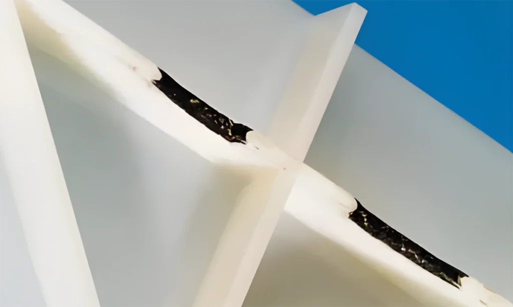
Burn marks refer to dark or black marks formed at the end of the flow path or in trapped gas areas during the injection molding process due to poor mold venting or too fast injection, where the air inside the mold does not have time to escape and suddenly heats up under high pressure (in extreme cases, temperatures can reach up to 3000 degrees). The overheated compressed air scorches the melt.
Do burn marks affect the product?
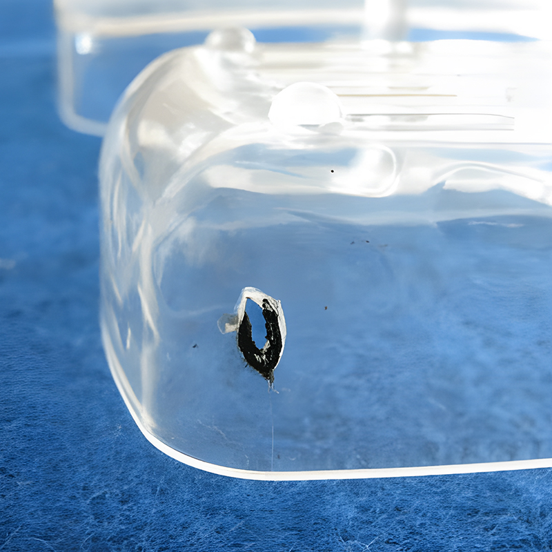
Burn marks on injection-molded parts can affect the appearance and quality of the product. The affected areas may show different colors and textures, such as turning black, yellow, or becoming rough, which can reduce the product’s aesthetic appeal; as shown in the picture below, the appearance is significantly affected after burn marks occur;
Burn marks on injection-molded parts may also affect the performance and reliability of the product. The affected areas may alter the physical and chemical properties of the injection-molded parts, such as reducing their strength, heat resistance, or corrosion resistance, which can affect the product’s usability;
Burn marks on injection-molded parts can also affect production efficiency and cost control; burn mark issues may lead to the scrapping or reworking of injection-molded parts, increasing production costs.
Causes of Burn Marks
1. Equipment-related Factors
a) Due to malfunction or damage to thermocouples, temperature control systems, and heating systems, causing localized overheating of the barrel,
b) Damage to the screw, diverter shuttle, and check ring, resulting in material retention.
c) Poor fit between the nozzle and the main runner bushing of the mold, causing abnormal shearing.
d) Gaps between the screw and the barrel, loosening of threaded connections within the barrel, causing melt retention and decomposition from prolonged heating.
e) Metal foreign objects stuck in the screw grooves or at the front of the barrel, causing abnormal material ejection and material decomposition.
2. Mold-related Factors
a) Poor mold venting, plastic being adiabatically compressed, and burning due to intense reactions with oxygen under high temperature and pressure.
b) Gate design and location should fully consider the melt flow state and mold venting performance when designing the mold.
c) Insufficient mold venting or incorrect positioning, as well as too fast filling speeds, cause adiabatically compressed air inside the mold to produce high-temperature gases, leading to resin decomposition and charring.
d) Mold vent holes blocked by mold release agents and impurities on the mold surface, causing poor venting.
3. Molding process-related Factors
a) Melt fracture leading to burn marks
Melt fracture can occur when the melt is injected into a large cavity at high speeds and pressures, causing the surface to experience transverse fractures and forming blisters, especially when a small amount of melt is injected into a large cavity.
The phenomenon arises from the elastic deformation of the polymer melt. As the melt flows within the barrel, the portion near the barrel wall, facing higher friction and slower flow speeds, is subject to significant stress. Upon ejection, this stress dissipates, but the central melt continues to flow at high speed, pulling along the slower-moving peripheral melt. This results in a rapid realignment of flow speeds and significant stress fluctuations across the melt. If the stress exceeds the melt’s capacity to withstand it, melt fracture occurs.
b) Impact of injection speed
When the melt is injected into the cavity at a slow speed, the flow state of the melt is laminar; when the injection speed increases to a certain level, the flow state gradually becomes turbulent. Generally, plastic parts formed under laminar flow conditions have a smoother and brighter surface, whereas under turbulent conditions, not only are surface blisters more likely to occur, but gas pockets are also more likely to form inside the plastic parts. Therefore, the injection speed should not be too high, and the melt should be controlled to fill the mold under laminar flow conditions.
c) Too high a temperature of the melt, which can cause the melt to decompose and char, leading to blisters on the surface of the plastic parts.
d) Material decomposition caused by excessively long stay times in the barrel during extended cycles.
4. Impact of raw materials
a) High content of moisture and volatile substances in the raw materials.
b) High melt index, good fluidity of the melt, making it difficult to expel gases.
c) Plastic additives, colorants containing volatile substances, and moisture, not resistant to high temperatures causing decomposition.
Improvement Measures for Burn Marks
1. Burn marks occur during empty injections
a) Check whether the nozzle is clogged.
b) Check whether there is damage to the screw, check ring, barrel, etc.
c) Check the heating system, temperature sensor lines, thermocouples, heating rings, and plasticizing temperature settings for abnormalities.
d) Check whether the raw material color powder, masterbatch, etc., contain easily decomposable substances, and consider replacing different materials to eliminate the issue.
e) Check if the back pressure is too high, the storage turn speed is too high, or the pre-plasticizing time is too long, causing raw material decomposition and carbonization.
2. Burn marks in the mold
a) For hot runner molds, check the hot runner itself and temperature control for abnormalities.
b) For cold runner molds, check the runner and gate for damage, etc.
3. Burn marks on the product
a) If burn marks occur at the edges of the product, consider increasing venting and reducing injection speed.
b) If burn marks occur in the middle of the product, consider changing the exhaust insert or adding an exhaust ejector pin, and use segmented injection in the process, reducing injection speed at the burn mark location.
c) If burn marks occur at the tail end of the product, we recommend cleaning the mold’s vent grooves and reducing the clamping force.
Case Analysis of Burn Marks
Product Introduction
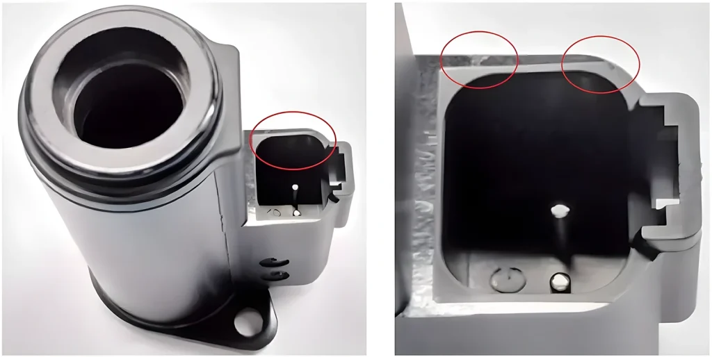
The image above shows a case of product burn marks. The right image is a close-up of the left image.
The product material is PBT, a type of connector product with thick walls and a secondary appearance surface. Due to high-quality requirements from the customer, noticeable surface defects on the product are not acceptable.
Molding conditions are as follows.
a. Mold molding temperature: 60~80℃.
b. Material temperature: 240~260℃.
c. Injection speed in three stages: first stage at 180mm/s, second stage at 135mm/s, third stage at 40mm/s.
d. Injection time: 1.5~3s.
e. Injection pressure: 1300~1500kgf/cm².
Product Issues
The product image shows slight burn marks inside the red circle, which the customer does not accept.
Reasons and Strategies
(1) Cause Analysis
During the initial mold trial, an analysis of the flow template was conducted, revealing that the location of the burn marks at the product’s end fusion line was mainly due to gases being unable to escape from the marked position in the mold cavity, causing trapped gas burn marks.
(2) Solution Strategies
Since the product and mold structures have already been confirmed by the customer and cannot be changed, the problem can only be addressed by adjusting mold venting and injection molding processes.
Expand the vent slots in the mold flow path, mold parting surface, and ejector pins as much as possible, reducing the end venting amount to alleviate the severity of burn marks.
Adjust the injection molding process to multi-stage injection. Due to the thickness of the product, use low speed or even lower speeds during the last two stages of injection to reduce the severity of burn marks.
Final Words
I am Lee Young from FirstMold, working diligently every day. Based on books, manuals, and workshop practical experience, I have summarized many sets of work experience for easy reference and learning. For those learning about injection molding, mold, product structural design, and mold design, it is important to read, practice, and try more, and not be afraid of failure. I hope my experience can help you.
