Splay marks are a common defect in injection molding production, appearing almost daily across various injection molding machines. The factors leading to this defect are numerous and complex. Some cases are easily resolved, while others may resist adjustment, causing significant waste and potentially delaying product delivery.
Today, I will cover everything about splay marks from a practical standpoint, offering insights for my peers and injection molding enthusiasts to effectively address real-world issues at the molding floor.
Since the occurrence of splay marks can be influenced by product design, I highly recommend product design companies, structural designers, and mechanical engineers gain a deep understanding of this issue. This not only helps in designing cost-effective and efficient new products but also facilitates setting acceptance standards with injection molding suppliers (for more details, see injection molding acceptance standards).
If you’re interested in other injection molding defects, feel free to click the following link for more information.
| Understand Different Injection Molding Defects | ||||
|---|---|---|---|---|
| Flash | Short Shot | Sink Mark | Warpage/Deformation | Burn Mark |
| Splay Mark/Silver Streak | Dark Spot/Black Speck | Flow Mark | Bubble | Weld Line |
| Color Difference/Uneven Color | Ejector Pin Mark | |||
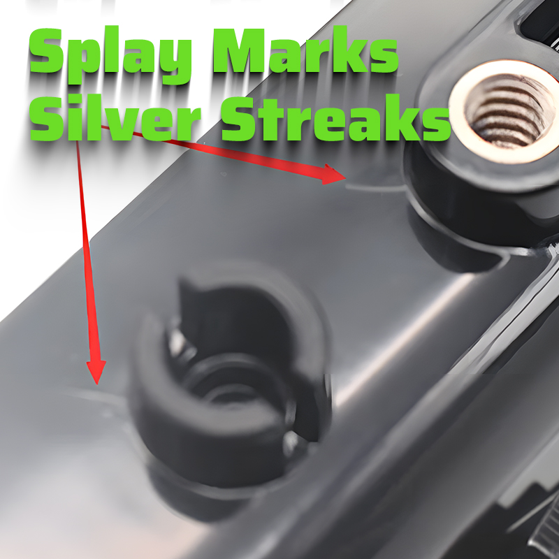
What are splay marks?
Splay marks, also called silver streaks, appear as flower-like spray patterns on the surface of molded parts near the gate or as bright, shiny V-shaped lines when light is cast obliquely on the parts.

In our injection molding production, splay marks / silver streaks are fundamental molding defects that can usually be quickly resolved through process adjustments. Unlike size and warping issues, which require cooling and solidification time to evaluate product quality, the cause of splay marks can sometimes be elusive, severely affecting production efficiency.
What causes splay marks?
Mold-related factors:
- The gate size is small.
- Poor mold venting leading to trapped gas splay marks.
- Sharp corners in gate and runner designs.
- Residual plastic in dead ends in hot runners.
- Improper placement or malfunction of hot runner temperature sensors.
- Blockages in hot runners.
- Water leakage in molds.
- Excessive temperatures in hot runners that are not precisely controlled.
- Nozzle tips with caps.
Machine setting factors:
- Improperly setting of back pressure for the melted plastic, too low causing moisture splay marks, too high causing thermal degradation splay marks.
- The injection speed is too fast.
- The initial injection speed or position is set incorrectly.
- Fast melt speed.
- No slow down at the end of the injection cycle.
- Partially blocked nozzle.
- The mold temperature is too low.
- Clogged parting line vents causing trapped air splay marks, needing cleaning every 4 hours.
- Overly high barrel temperatures.
- The nozzle temperature is too low.
- Inappropriately set drying temperature or insufficient drying time causing moisture splay marks.
Design-related factors:
- Non-smooth gate design causing residual material splay marks.
- gate and runner dimensions are too small.
- Improper gate type (pin, square, round, fan-shaped) or size.
- Poorly designed vent locations on the parting surface or insufficient vent depth or quantity.
- Significant differences in wall thickness.
- Improperly positioned gate.
- Lack of vents behind the flow path in mold design.
- Inadequate vent channels in mold flow analysis.
Machine-related factors:
- Poor matching of nozzle to mold sprue.
- Malfunctioning heating elements or fans in the hopper.
- Abnormal heating in the barrel.
- Malfunctioning back pressure valve.
Material-related factors:
- Incorrect drying temperature and time for the material.
- Contaminants in the material.
- Unevenly sized material particles.
- Mixing different batches of modified material from different suppliers.
- Dirty gates or excessive dust.
Types of splay marks
Given the reasons mentioned above, I categorize splay marks as follows:
1. Hydrolytic splay marks (Moisture Splay Marks)
These occur when plastic undergoes hydrolysis in the barrel due to moisture in the material before molding, or when adequately dried material absorbs moisture while sitting in the hopper without effective insulation. This excessive moisture content, when subjected to high temperatures in the barrel, turns water into steam, degrading the resin and forming carbon dioxide gas trapped within the molten resin. This gas rushes into the mold cavity during injection, creating hydrolytic silver streaks, significantly reducing the strength and brittleness of the molded part. These are fairly common and easy to identify, usually distributed evenly along the direction of injection and densely populating the surface in severe cases.
The fundamental remedy for hydrolytic splay marks is thorough drying of the material, ensuring that the moisture content in the pellets used during molding is controlled below 0.03%. Therefore, the drying process conditions must be strictly managed, and the moisture content of the pellets should be verified by air-shot before molding.

The moisture content of materials
Since the moisture content of materials can cause so many serious problems, is there a unified cautionary line for the moisture content in injection molding? Unfortunately, no! The moisture content of each material varies greatly, and the degree to which it can be “dehydrated” also varies. The table below is a collection of common plastics and their moisture content:
| Plastic | Moisture Content | Permissible Moisture Content for Injection Molding |
|---|---|---|
| PE | 0.1%~0.2% | 0.05% |
| PP | 0.1%~0.3% | 0.07% |
| HDPE | 0.1%~0.2% | 0.05% |
| LDPE | 0.1%~0.2% | 0.05% |
| LLDPE | 0.1%~0.2% | 0.05% |
| PVC | 0.1~0.4% | 0.07% |
| GPPS | 0.1~0.3% | 0.07% |
| HIPS | 0.1~0.3% | 0.07% |
| AS, SAN | 0.20.3% | 0.07% |
| ABS | 0.40% | 0.07% |
| PMMA | 0.40% | 0.07% |
| PET | 0.3%~0.4% | 0.02% |
| PBT | 0.1%~0.25% | 0.02% |
| PA6 | 1.30% | 0.019 |
| PA66 | 1.50% | 0.01% |
| PC | 0.30% | 0.02% |
| POM | 0.12%~0.25% | 0.02% |
| PPO(NORYL) | 0.14% | 0.02% |
| PPO(SE-100) | 0.37% | 0.02% |
| PPS | 0.10% | 0.05% |
| PS | 0.1~0.3% | 0.07% |
| PC/PBT | 0.50% | 0.05% |
| PC/ABS | 0.50% | 0.06% |
Dehydration
Generally, to quickly dehydrate, most plastic materials need to be baked before injection molding. Since the initial moisture content in plastic particles is relatively low, the drying process belongs to trace moisture drying, and hot air is generally used as the drying medium.
There are two methods of baking according to production needs. One is for small batch materials and non-continuous baking, which can be done in baking ovens. The more common continuous baking method uses two types of equipment: hot air dryers and dehumidifying dryers. The cost varies for each industry.
Hot air dryer
Suitable for small batch materials, and one oven can bake multiple types of raw material particles simultaneously. It has high temperature control accuracy, low equipment investment, and easy operation. It is generally suitable for the injection molding needs of small appliances and electronic consumer goods.
Hot air drying machine
Suitable for large batch raw material usage, easy to operate, relatively low investment cost, and good drying effect in low humidity environments. However, during the rainy season, the defect rate often increases sharply. Therefore, manufacturers in the southern region need to pay special attention.
Dehumidifying dryer
Based on the hot air dryer, it requires an additional dehumidifier to remove moisture from the air, increase drying efficiency, and is especially suitable for rainy days and the use of high moisture content PA materials.
As for the baking process, you can think of it as similar to cooking, where the “degree of heat” is equally important. If the baking time is too long, it will cause discoloration and degradation of the material; if the drying temperature is too low, it will cause the moisture content of the material to exceed the standard. I have also summarized a table of baking times for plastics:
| Plastics | Baking Temperature | Baking Time |
|---|---|---|
| PE | 60~80°C | 1~2h |
| PP | 80~100°C | 1~2h |
| HDPE | 60~80°C | 1~2h |
| LDPE | 60~80°C | 1~2h |
| LLDPE | 60~80°C | 1~2h |
| PVC | 60~80°C | 1~2h |
| GPPS | 80~90°C | 2~3h |
| HIPS | 80~90°C | 2~3h |
| AS/SAN | 80~90°C | 2~4h |
| ABS | 80~90°C | 3~4h |
| PMMA | 80~90°C | 3~4h |
| PET | 130~140°C | 4-6h |
| PBT | 130~140°C | 3~4h |
| PA6 | 80~100°C | 4~6h |
| PA66 | 80~100°C | 4~6h |
| PC | 120°C | 3~4h |
| POM | 80-90°C | 2~4h |
| PPO(NORYL) | 120°C | 2~4h |
| PPO(SE-100) | 95°C | 2~4h |
| PPS | 120°C | 3~4h |
| PS | 80~90°C | 2~3h |
| PC/PBT | 100~120°C | 3~4h |
| PC/ABS | 80~100°C | 2~3h |
2. Thermal Degradation Splay Marks (Thermal Silver Streaks)
These occur when resin overheats during the molding process, generating gases such as carbon dioxide, which cause silver streaks on the surface of the molded parts.
Common causes include:
1. Excessively high barrel temperatures.
2. Residual plastic in dead ends in the barrel or nozzle.
3. Prolonged residence time in the barrel.
4. Reduced molecular weight of the resin due to excessive use of regrind, thereby compromising the impact strength and making the material too brittle for use.
5. The back pressure is too high.
Thermal silver streaks are typically identifiable by their appearance, which does not follow a specific pattern and sometimes resemble a comet. They are often accompanied by a darkening of the plastic’s color, especially noticeable along the sprue, which serves as a primary indicator for identifying thermal silver streaks.
Appropriate measures should be taken based on the cause of degradation. If caused by an overly high temperature in a section of the barrel, that section’s temperature should be reduced; if caused by dead spots in the barrel or nozzle, those areas should be cleaned and dead spots eliminated; if due to prolonged residence time in the barrel, the molding cycle should be as short as possible while still ensuring product quality. If these measures are ineffective, consider using a smaller-capacity injection molding machine for production.

3. Structural silver streaks:
These are caused by poor structural design of the molded parts, such as severe unevenness in wall thickness or abrupt changes in section, causing the molten material to expand or shrink abruptly during the filling process, allowing air to mix into the molten material in the mold cavity. Structural silver streaks mainly affect appearance and have little impact on the strength and impact toughness of the molded parts.
The characteristics of structural silver streaks include a fixed distribution of streaks in shape and location when process conditions are constant, generally along the direction of injection and often occurring after abrupt section changes. Since structural silver streaks are caused by abrupt section changes and severe unevenness in wall thickness, they often appear on the surface of the molded parts along with sink marks defects and may even cause varying degrees of bubbles inside the parts.
Structural silver streaks can generally be eliminated by changing the injection speed. When the sectional change is small, the injection speed can be reduced, allowing the material to fill the mold cavity smoothly and preventing air from mixing in as it passes through the abrupt section, thus avoiding the formation of silver streaks. However, reducing the injection speed may also lead to short shots, necessitating adjustments to other process conditions such as mold temperature and nozzle temperature for resolution. When the sectional change is significant, a higher injection speed may be attempted, along with an increase in injection pressure to force the air out from the parting surface.
If adjusting the injection speed or increasing the injection pressure does not resolve the issue, consider improving the structural design of the plastic parts and enhancing the mold venting system.

4. Gate and Runner Design Splay Marks:
These are caused by the irrational design of the gating system or local blockages. Their causes and solutions are as follows:
1) The sprue’s cone angle is designed to be too large
If the cone angle of the sprue is too large, it causes the material to leave the cone wall at the beginning of injection, creating a gap. As the mold cavity fills, air mixed into the material flow enters the mold cavity, forming silver streaks. These streak marks are characterized by their distribution entirely along the direction of injection.
To eliminate this defect, first, perform a dry cycle to rule out the possibility of resin hydrolysis and degration, then check whether the size of the sprue cone angle is appropriate. If the A-angle is greater than 10 degrees, it may cause the above phenomenon. An A-angle of 4~6 degrees is suitable; if the A-angle is too small, it may cause demolding difficulties and poor material flow. Runner silver streaks are sometimes eliminated by changing the injection speed, but the fundamental method is still to modify or replace the sprue bushing to reduce the sprue cone angle.
2) Irrational gate design
If the gate cross-sectional area is too small, it causes turbulent flow or jetting as the material passes through the gate, mixing the molten material with air and producing silver streaks near the gate. These streak marks are characterized by a radial distribution centered on the gate. Their elimination method involves enlarging the gate or changing the cross-sectional shape of the gate to make the silver streaks disappear. While modifying the gate, if the injection speed is appropriately reduced, it will be more effective.
3. Cold material at the nozzle tip causes part of the gating system or local blockage during injection
The mechanism of silver streak formation due to a partial blockage in the runner or gate is similar to that caused by a too-small gate. When identifying such silver streaks, traces of cold material should be found in the gating system. The method to eliminate this defect is to enlarge the cold slug well in the mold and increase the nozzle temperature.

5. Pulsation silver streaks:
So-called pulsation silver streaks do not refer to the streaks themselves pulsating, but to the uneven jumping phenomenon that occurs during the retraction and feeding of the pre-plasticizing screw, resembling a pulse. This phenomenon mainly reflects the abnormal dropping of material, whereby air easily enters the barrel and is carried into the mold cavity with the molten material during injection, forming silver streaks.
These streaks are characterized by irregular occurrences in terms of location and quantity, sometimes accompanied by short shots, sink marks, and internal bubbles.
The method to eliminate pulsation silver streaks involves taking corresponding measures based on the cause of the pulsation.
Their causes and solutions are as follows:
1). The temperature at the rear end of the barrel is too high, causing the material particles near the feed port to stick together and drop abnormally. We should reduce the temperature at the rear end of the barrel.
2). The material temperature is too low, causing poor plasticization of the resin and excessive load on the pre-plasticizing motor, resulting in abnormal screw speed. we should increase the molding temperatures appropriately to enhance plasticization.
3). The back pressure of the screw is too low; for PC material, the back pressure should be 10-25Mpa.
4). The hopper insulation device is in improper setting up or using. Infrared bulbs should not be too close to the material particles or used for too long, causing the particles to stick together at high temperatures and drop.
Sometimes, a sudden pulsation occurs during normal production, often due to individual automatic control instruments malfunctioning or failures in the barrel heating device, causing abnormal temperatures at the rear end of the barrel. Therefore, while adjusting the temperature, it is also necessary to check whether there are any abnormalities in the instruments and circuits.

6. Trapped air silver streaks:
Trapped air silver streaks refer to streaks formed by gases that cannot be expelled during the material-filling process. We characterize these streaks by fairly obvious weld lines, with the silver streaks often appearing near the weld lines, while other areas do not have silver streaks.
The fundamental method to eliminate these silver streaks involves changing the gate location and type, setting effective venting slots, or modifying the plastic part structure, but this requires significant modifications to the mold. In practical production or trial molding, corrective process conditions are often adopted, such as adjusting the injection pressure and speed and changing the temperature difference between the stationary and moving molds.

Case study of a splay mark defect
Product information:
1. Name: Speaker shell
2. Material: High brightness ABS gray
3. Size: 20mm x 5mm x 4mm
4. Cavity: 1*2
5. Weight: 87g*2
6. Gate: Submarine type
Injection molding process:
1. Injection molding machine model: Haitian 450T
2. Nozzle temperature: 215°C
3. Barrel temperatures: 230°C-220°C-200°C-190°C-170°C
4. Mold temperatures: Cavity 55°C, core 45°C
5. Molding time: 45 seconds, cooling time 18 seconds
6. Injection time: 3.2 seconds
7. Metering stroke: 150mm
8. Retraction time: 0.3 seconds
9. Segmented injection: 4 stages
10. Injection pressures: 90-110-90-50
11. Injection speeds: 20-45-30-5
12. Injection positions: 142-130-122-0
13. Segmented holding pressure: 2 stages
14. Holding pressures: 15-72
15. Holding times: 10-20
16. Holding duration: 2 seconds-6 seconds

Product processing method:
Produced using an automatic robot, ABS material mixed with gray masterbatch, pre-dried before production at a drying temperature of 85°C.
Product quality requirements:
This product is intended for appearance use and must not have any surface scratches, sink marks, flow lines, splay marks, or other defects. Dimensional tolerance must not exceed 0.02; exceeding this tolerance can lead to assembly issues.
Production defect information:
During production, splay marks appeared near the gate, affecting the surface appearance of the product. After exposure to sunlight, delamination occurred, also affecting the product’s dimensions, as well as its mechanical and chemical properties. This severely impacts the quality and lifespan of the plastic parts.
Products with this defect are considered defective, and process engineers should quickly make adjustments to avoid batch defects that could delay production capacity, waste energy, and delay order delivery.
Solution:
The analysis demonstrated that overflow occurred in the production of a set of molds used for manufacturing, with material wrapping around the nozzle and the first and second heating rings of the barrel. The heating rings for the nozzle and the first section of the barrel were damaged and have been replaced. During the replacement of the heating rings, the thermocouple was not clamped tightly and shifted backward, causing the actual material temperature to be higher than the set temperature, even though the material temperature settings were the same.
This means that the actual material temperature was higher than during the previous production, and since the current production used a submarine-type gate, the same barrel temperature (material temperature) necessarily increased the shear rate, causing the material to decompose and produce splay marks. It is necessary to adjust the material temperature and re-fix the heating rings and clamp the thermocouple.
Conclusion
Splay marks / Silver streaks are a common production issue. We can resolve them through various methods such as adjusting injection pressure, mold temperature, and replacing plastic materials. The key is to identify the cause of the splay marks and take appropriate measures based on the specific circumstances. Through effective solutions, we can reduce the impact of splay marks on the production process significantly, improving the efficiency of injection molding machines.
I am Lee Young from FirstMold, with over a decade of experience in the mold injection industry, having dealt with thousands of clients and product managers. My continual contact has made me realize: achieving high-quality production of products or parts requires collaborative efforts between designers and producers. I have always enjoyed sharing various industry knowledge, hoping my experience can help you.