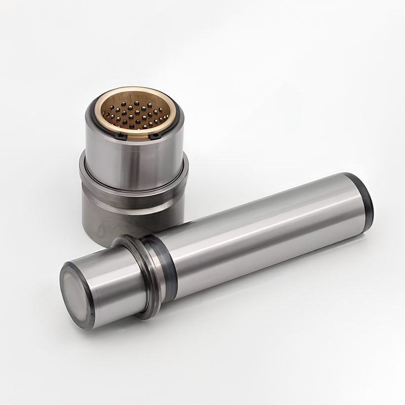
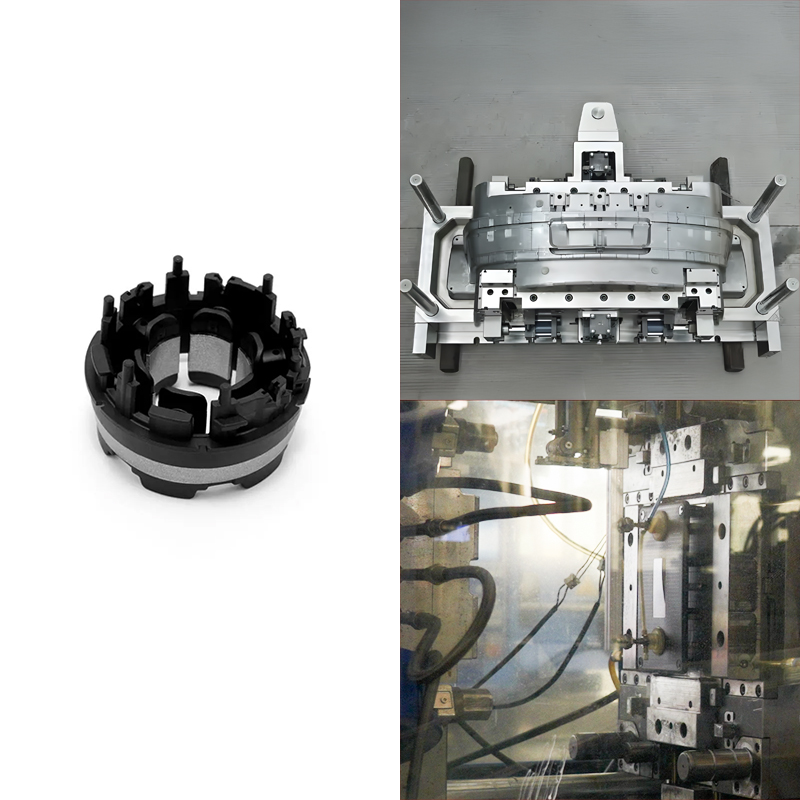
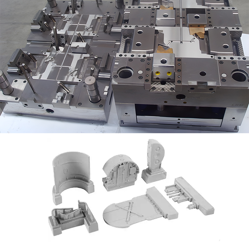
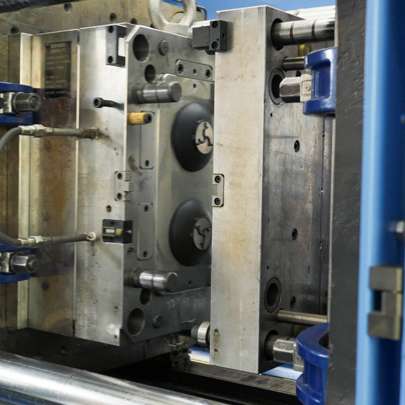
Injection molds have an important guiding system, primarily consisting of guide pins and guide bushings. As guiding devices, they require attention during purchase (or manufacture), design, and assembly.
This article provides a detailed introduction to guide pins and guide bushings. It’s a pleasure for mold enthusiasts to keep it for reference.

What Are Guide Pins and Guide Bushings in Molds?
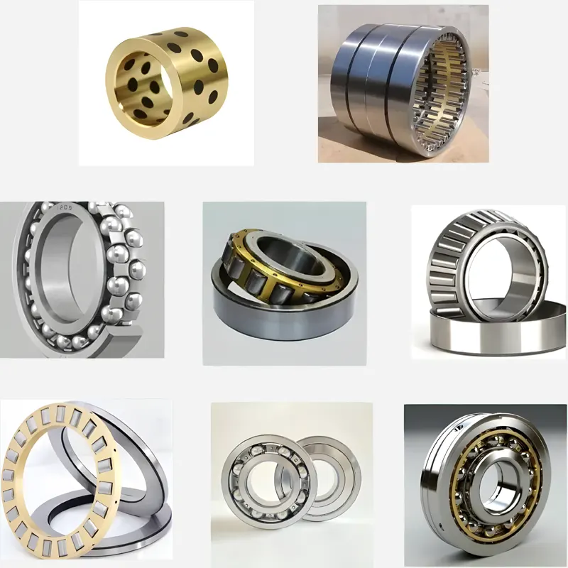
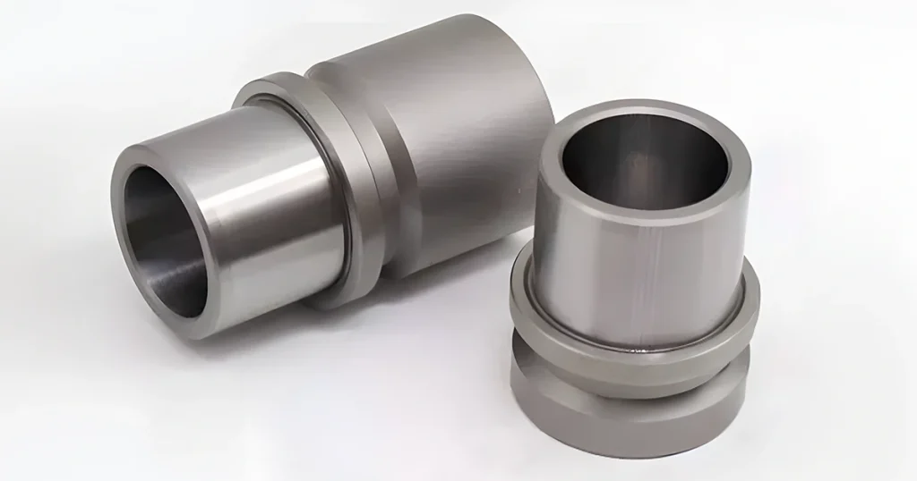
Guide pins and guide bushings are commonly used precision fitting components in mold manufacturing. They are mainly for positioning and support during processing. Guide pins are usually long, strip-like parts with various shapes, but they are generally cylindrical or square. Guide bushings are the sleeves for guide pins and come in various shapes as well.

Fitting Methods of Guide Pins and Guide Bushings
There are multiple fitting methods, with the most common being clearance fit and interference fit. Clearance fit leaves a certain gap between the guide pin and bushing to reduce deformation caused by thermal expansion and contraction. Interference fit involves tight contact with pressure between the guide pin and bushing, providing more robust support and positioning.
Functions of Guide Pins and Guide Bushings
They primarily serve two functions in machining:
Positioning: Through precise processing and matching, they ensure accurate positioning, allowing the parts being processed to be machined and handled according to predetermined positions.
Preventing Jitter: In machining, vibrations, and shocks often cause part jitter and deviation. The fit between them prevents this, ensuring machining accuracy and quality.
Types of Guide Pins and Bushings
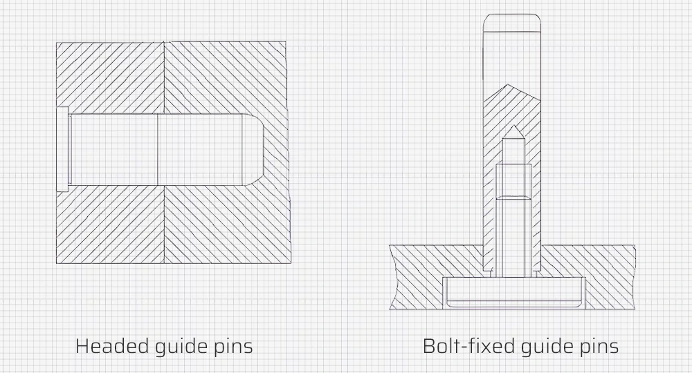
Common guide pins include headed guide pins and bolt-fixed guide pins.
We can categorize bushings into straight bushings (a) and headed bushings (b, c, d).
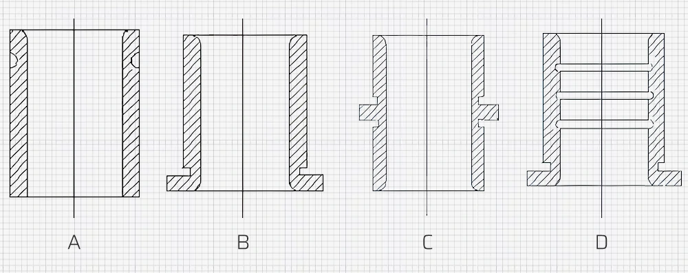
- Figure a: Straight bushing, used in situations requiring a short guiding hole length or where the template is too thick.
- Figure b: The end head is riveted to prevent the straight bushing from being pulled out by the guide pin.
- Figure c: Headed bushing used when the template thickness does not meet the guiding hole length requirement. We need to install it with a looser fit than the primary template.
- Figure d: Grooved bushing, used to reduce friction when the diameter is large.
Arrangement In the Mold Design
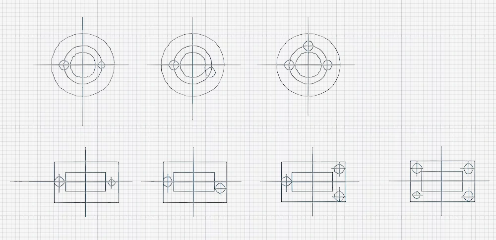
A mold typically has 2-4 guide pins. Small or portable molds usually have 2. Medium to large molds have 3-4 with 4 being the common configuration.
To achieve the principle of a unique mold closing direction, We usually arrange them in two ways:
- Symmetrically distributed, with varying diameters for one of the guide pins.
- Asymmetrically distributed, with identical diameters but one guide pin positioned asymmetrically.
For stable guidance, it is preferable to place the guide pins farther apart, usually outside the cavity. The distance from the guide hole wall to the template edge should not be too close, generally slightly larger than the guide pin radius.
Acquisition of Guide Pins and Bushings
Purchased from External Suppliers
Most mold manufacturers purchase guide pins and bushings as standard parts. This saves time, allowing manufacturers to focus on processing the core cavities and inserts, thus improving production efficiency. Given China’s extensive manufacturing industry, the supply chain for various mold components is well-developed, making external processing of guide pins and bushings affordable.
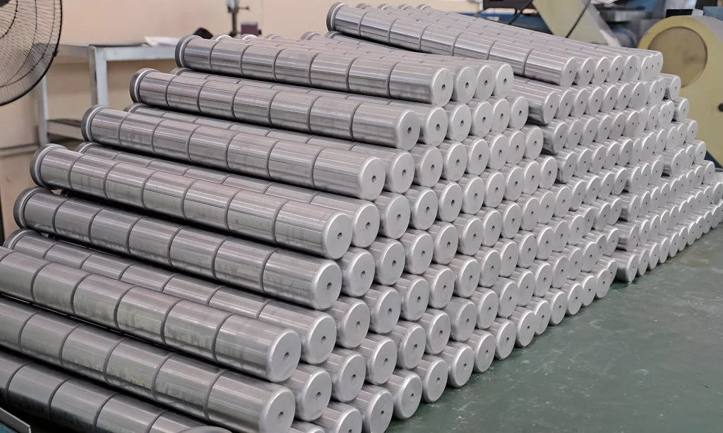
In such cases, manufacturers need to make accurate judgments on the quality of guide pins and bushings, focusing on aspects like:
- Product Quality: The stability of product dimensions, surface finish, and material utilization reflect the quality of the mold itself.
- Service Life: The number of work cycles or produced parts a mold can complete while ensuring product quality.
- Ease of Use and Maintenance: Convenience of use, minimal auxiliary production time, and ease of maintenance.
- Maintenance Costs and Cyclicity: The cost and frequency of maintenance are also considered in assessing mold quality.
Produced In-House by Mold Component Companies
Based on their structural shape, size, and material requirements, people can select appropriate round steel as blanks.
Processing of Guide Pins
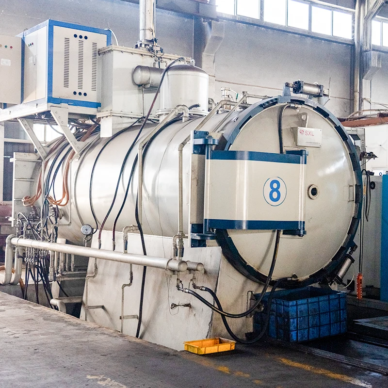
Guide pins typically use 20 steel, roughly processed on a lathe, heat-treated (carburized to a depth of 0.8-1.2mm, hardened to 58-62HRC), and finish-ground externally. To further improve dimensional accuracy and surface roughness, perform additional grinding after leaving a 0.01-0.015mm margin post external grinding.
If using a lathe for clamping and grinding guide pins, we commonly use a clamp. A uniform layer of abrasive is applied to the ground surface, and the guide pin is fitted with a grinding ring for manual axial reciprocating motion. The guide pin rotates circumferentially driven by the spindle, achieving grinding. Alternatively, use a grinding disc for mass production.
Processing of Bushings
After rough turning, leaving a grinding margin of 0.3mm, bushings undergo heat treatment (carburizing 0.8-1.2mm deep, hardened to 58-62HRC) and internal and external grinding. Due to the high precision and coaxiality required for matching them, internal grinding is done first, followed by fitting with a mandrel for external grinding. If the external grinding is not critical, omit it. When internal grinding leaves a 0.01-0.015mm margin, you may need further honing for precision.
Customizing Guide Pins and Bushings
When custom ordering guide pins and bushings, mold companies should consider the following:
1. Material Selection
Guide pins and bushings are typically made from metals like carbon steel, alloy steel, or stainless steel. The material choice should account for the working environment and frequency of use, favoring materials with high hardness, wear resistance, and corrosion resistance.
2. Dimensional Precision
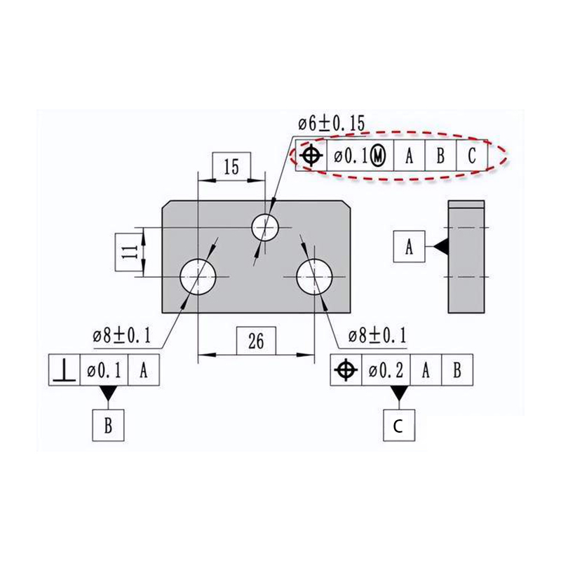
Custom orders must adhere strictly to the dimensional accuracy specified in the drawings. High precision is essential to avoid assembly and usage issues.
3. Processing Precision
The precision of guide pin and bushing processing directly affects their fit and service life. High-precision machining is especially critical in fields like electronics and optics.
4. Surface Quality
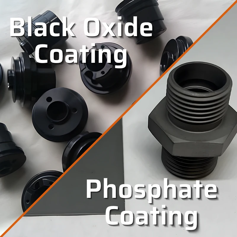
High surface quality is necessary for longevity and effectiveness. Surface treatments should prevent corrosion and damage, maintaining the components’ performance.
5. Lubrication Method
Appropriate lubrication methods enhance the sliding and wear resistance of guide pins and bushings. Special mold lubricants, known as “non-seepage lubricants,” ensure long-term durability.
6. Maintenance
Regular maintenance, cleaning, and lubrication are essential to sustain the accuracy and performance.
Assembly of Guide Pins and Bushings
In design and assembly, they must fully close before the punch contacts the workpiece or the pressure plate touches the workpiece. Ensure a 10-15mm gap between the top of the guide pin and the upper mold base’s surface. After assembly, a 2-3mm gap should remain between the guide pin and the lower mold base’s lower surface and between the bushing’s top end and the upper mold base’s upper surface.
For symmetrical workpieces, different diameters or positions for guide pins avoid directional errors during assembly. Large lateral pressures require thrust pads on the mold base to prevent guide pins and bushings from bearing side forces. Bushings should have vent holes to release trapped air.
Conclusion
This concludes the discussion on guide pins and bushings. FirstMold is a professional mold and injection company with experienced staff knowledgeable in every detail. If you wish to discuss industry knowledge, contact us at [email protected]. For part production and manufacturing needs, click the link to submit your requirements.
