Before understanding or learning CNC programming, we should first clarify what knowledge we need to master.
What skills or knowledge should you get before understanding or learning CNC programming?
1. Having a mechanical foundation and knowledge of mold structure can be beneficial, as it provides a better understanding of machining processes and the components being programmed.
2. CNC programming encompasses both manual programming and Automatic programming. Manual programming often involves writing code directly, requiring a foundation in mathematics and a clear understanding of coordinate directions (X, -X, Y, -Y). This knowledge is crucial for accurate programming.
3. While learning 2D quick drawing and 3D design can help understand the visual aspects of CNC programming, it is not necessarily a prerequisite. It depends on the specific goals and projects.
4. Having a passion for machinery and being interested in the performance and operation of specific machine brands (such as Sanling, FANUC, Siemens, and HASS) can enhance motivation and engagement with CNC programming. Nevertheless, comprehending or mastering the programming itself does not necessitate its mandatory requirement.
5. Observing the actual operation of CNC machines on-site, including aspects such as tool speed, feed rate, and depth of cut, can provide valuable insights and practical knowledge that can enhance CNC programming skills.
6. Diligent learning, critical thinking, taking thorough notes, and learning from mistakes are essential for effective learning and mastery of CNC programming or any skill.
Which software tools are utilized in CNC programming?
| Software Category | Software Name |
| Computer-Aided Design (CAD) | AutoCAD, SolidWorks, Fusion 360, CATIA, Siemens NX |
| Computer-Aided Manufacturing (CAM) | Mastercam, CAMWorks, PowerMill, GibbsCAM, Edgecam |
| G-code Editors | Notepad++, Visual Studio Code, Gedit, Sublime Text |
| Simulation and Verification | Vericut, NCSIMUL, CAMotics, MachineWorks |
| Machine Control and Communication | Fanuc CNC Guide, Siemens Sinumerik Operate, Haas Control Simulator, Mach3 |
Manual programming and Automatic programming in CNC programming
As mentioned above, in CNC programming, there are two main approaches to creating programs: manual and automatic.
Manual Programming:
Manual programming involves directly writing the CNC program code using a text editor or specialized software. The programmer needs to understand the CNC machine’s capabilities, the G-code language, and the specific syntax required by the machine controller.
The manual programming process typically involves:
Writing individual lines of G-code instructions to define tool movements, spindle speeds, feed rates, and other parameters.
Calculating precise coordinates for tool paths based on the part geometry using mathematical calculations and trigonometry.
Considering tool changes, workpiece setup, tool offsets, and other factors to ensure accurate and efficient machining operations.
Manual programming allows precise control over the machining process, enabling customization and fine-tuning of the code. It is often used in complex or unique machining applications where automatic programming may not be suitable or efficient.
Automatic Programming:
Automatic programming, or computer-aided programming or CAM programming, involves using specialized software to automatically generate CNC programs. The software generates the program code by using inputs such as part geometry, tooling information, machining operations, and other parameters.
The automatic programming process typically includes the following:
Importing or creating a 3D model or CAD file of the part to be machined.
Defining the machining operations, tooling, and machining parameters within the CAM software.
The software automatically generates the CNC program code, including tool paths, speeds, feeds, and other instructions.
Automatic programming offers several advantages, including increased productivity, reduced programming time, and the ability to simulate and optimize tool paths before machining. It is commonly used in industries with high-volume production or repetitive machining tasks.
Both manual programming and automatic programming have their own merits. They are used based on the project’s specific requirements, the complexity of the part, the programmer’s expertise, and other factors. Many CNC programmers use manual and automatic programming techniques to achieve the best results.
Steps of CNC programming
Workflow of the manual programming
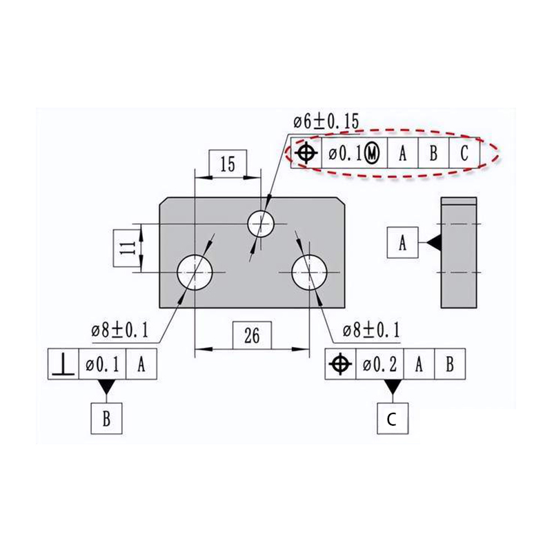
1. Analysis of the part drawing and process planning: This involves analyzing the part drawing, understanding the dimensions and technical requirements, determining the processing plan, sequencing the operations, designing fixtures if necessary, selecting appropriate tools, and planning the tool path and cutting parameters.
2. Mathematical processing: A workpiece coordinate system is established based on the geometric characteristics of the part. The tool trajectory is calculated within this coordinate system, considering the starting and ending points of geometric elements, circular arc centers, and intersections or tangent points between geometric elements. For complex shapes, discrete points on the surface or curve are calculated, and straight lines or arc approximations are used to connect these points.
3. Writing the part program list: The determined processing route and process parameters are translated into the CNC system’s command code and program segment format. The part program is written line by line, following the specified programming syntax and conventions.
4. Program input: In the past, program input was done using perforated paper tape, but modern CNC machines typically use keyboards or computer interfaces to input the program code into the CNC system.
5. Program verification and the first test cut: The written program must be verified and tested before machining. Verification involves checking the machine’s motion trajectory by running the program without cutting the workpiece, often using a pen to trace the tool path on paper. If the CNC machine has graphic display capabilities, simulation can be used to visualize the tool-cutting process. However, the first test cut on the actual workpiece is crucial to assess the accuracy of the machined parts and make necessary adjustments to cutting parameters and tool paths.
Workflow of the Automatic programming
1. CAD Model Import or Creation
The first step is to import a 3D model of the part to be machined into the CAM software. The 3D model can be imported from CAD software or created directly within the CAM software.
2. Define Machining Operations
Next, the programmer defines the machining operations to be performed on the part. This includes specifying operations such as roughing, finishing, drilling, contouring, pocketing, etc. Each operation has specific parameters such as tool selection, cutting speeds and feeds, cutting depths, stepovers, and allowances.
3. Toolpath Generation
Based on the defined machining operations, the CAM software generates a toolpath representing the tool’s movement and machining strategy on the part’s surfaces. The toolpaths are calculated by considering factors such as the tool’s geometry, tool orientation, collision avoidance, and optimization algorithms.
4. Simulation and Verification
Once the toolpaths are generated, the programmer can simulate the machining process within the CAM software. This simulation allows for visualizing the tool’s movement, detecting any potential collisions or errors, and ensuring the toolpath is optimized and suitable for the part.
5. Post-Processing
After the toolpath is finalized and verified, the CAM software performs post-processing. This involves converting the toolpath into machine-specific G-code instructions that the CNC machine can understand. The post-processor tailors the G-code output to match the particular syntax and formatting requirements of the target CNC machine controller.
6. Transfer to CNC Machine
The generated G-code program is transferred to the CNC machine through a direct connection or external storage media such as USB drives or network transfers. The program is loaded into the machine’s controller, ready for execution.
7. Machine Setup and Execution
The machine is set up before running the CNC program with the appropriate work-holding fixtures, cutting tools, and workpiece alignment. Once everything is in place, the CNC program is executed, and the machine carries out the programmed machining operations on the workpiece.
different code in the CNC programming
G-codes (Preparatory Codes)
G-codes are used to define various preparatory functions and operations. These codes specify the tool’s movement, machining modes, coordinate systems and other parameters. Some common G-codes include G00 (rapid positioning), G01 (linear interpolation), G02/G03 (circular interpolation), G17/G18/G19 (plane selection), and G90/G91 (absolute/incremental positioning).
M-codes (Miscellaneous Codes)
M-codes are used to control miscellaneous machine functions, such as spindle operation, coolant on/off, tool changes, and machine stops. They vary depending on the machine’s make and model. Examples of M-codes include M03/M04 (spindle on clockwise/counter-clockwise), M05 (spindle stop), M06 (tool change), and M08/M09 (coolant on/off).
T-codes (Tool Selection)
T-codes are used to specify the tool number or tool offset to be used for machining. These codes indicate which tool in the tool magazine or tool holder should be engaged for a particular operation. For example, T01 selects tool number 1, T03 selects tool number 3, and so on.
S-code (Spindle Speed)
S-code is used to define the desired spindle speed for the machining operation. The value following the S-code represents the spindle speed in RPM (revolutions per minute). For example, S1000 sets the spindle speed to 1000 RPM.
F-code (Feed Rate)
F-code is used to specify the feed rate at which the tool moves along the programmed tool path. The value following the F-code represents the feed rate in units per minute. For example, F200 sets the feed rate to 200 units per minute.
X, Y, Z, and other Axis Codes
These codes specify the coordinates and positions of the tool along different axes. The X-code represents the position along the X-axis, the Y-code represents the position along the Y-axis, and the Z-code represents the position along the Z-axis. Additional axis codes may be used for machines with more axes, such as A, B, C, etc.
Dwell Codes
Dwell codes pause the machine at a specific location or duration. The dwell time is specified using the P-code, representing the dwell time in seconds. For example, G04 P2 would cause the machine to dwell for 2 seconds.
Among the different codes used in CNC programming, the G-code is the most commonly used. G-codes are fundamental to CNC programming as they define the machine’s movement and control various aspects of the machining process.
Final Word
CNC programming involves numerous crucial considerations that deserve careful attention. Given the opportunity, I intend to dedicate an article in the future to comprehensively discuss the key aspects that require attention in CNC programming.

