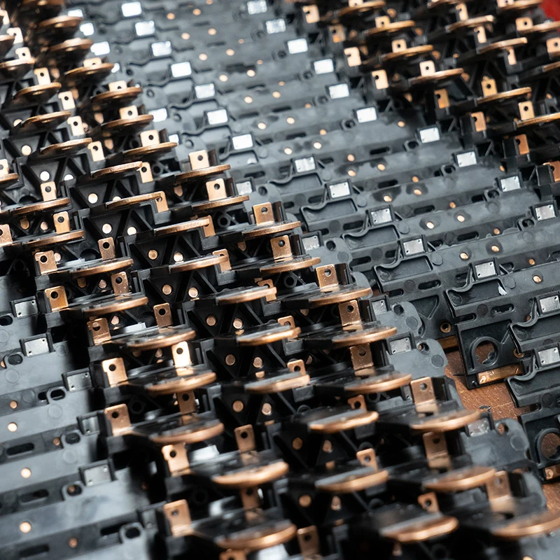
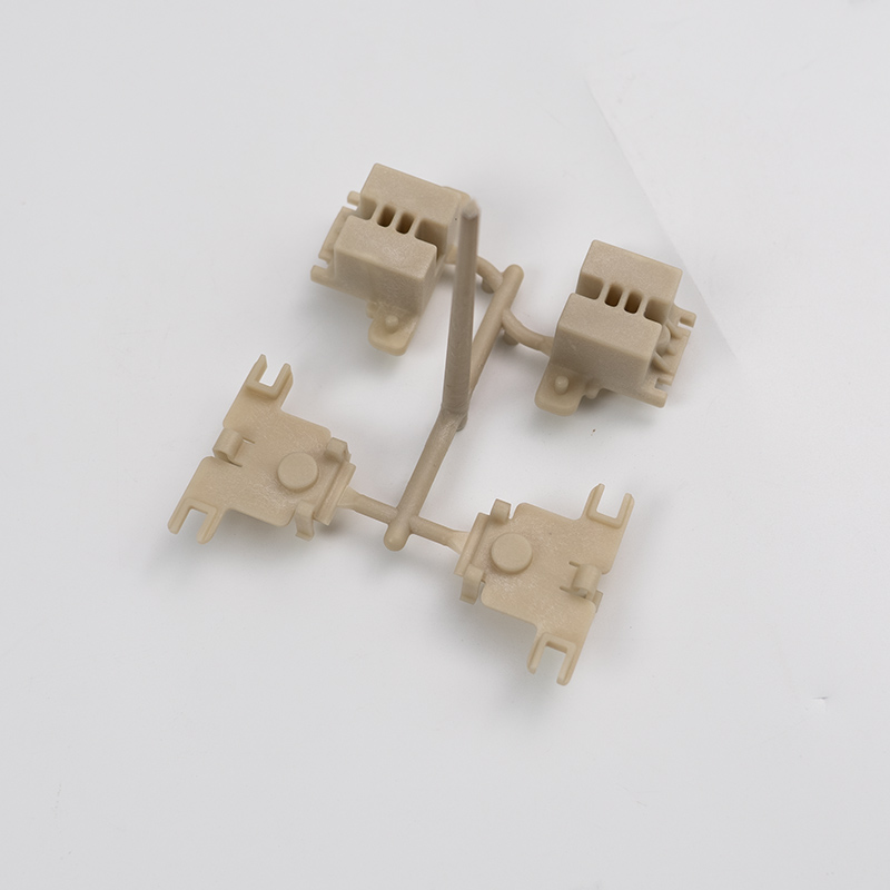
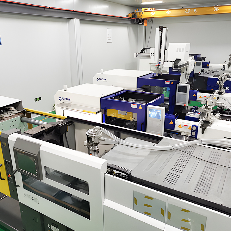
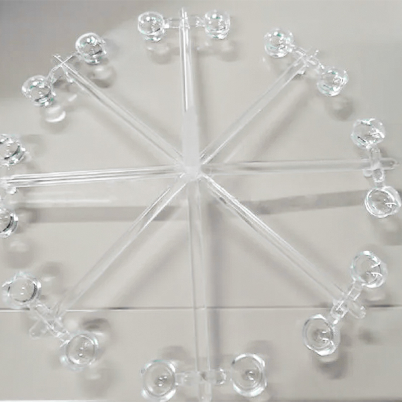
Injection molding defects are issues that every injection molding factory may encounter during the molding process. Flash is a common injection molding defect.
For product or structural designers, understanding flash and other injection molding defects helps them improve their design methods and accept finished products or parts from injection molding factories (refer to injection molding acceptance standards).
For mold and injection molding factories, analyzing flash and solving this defect perfectly is a fundamental skill. Every mold and injection molding practitioner has the responsibility and obligation to master all injection molding defects.
Below is a table of common injection molding defects and their links, which interested friends are welcome to click on for in-depth understanding:
What is Flash in Injection Molding?
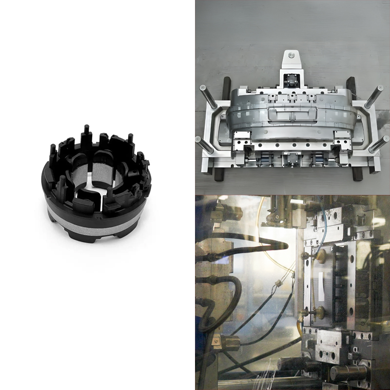
Flash on plastic parts, also known as burrs or spews, refers to the extra material produced during the molding process when the plastic melt enters the gap of the mold. This extra material is usually located on the edge or surface of the plastic part and appears sharp, hence the name “flash” — as shown in the image below:

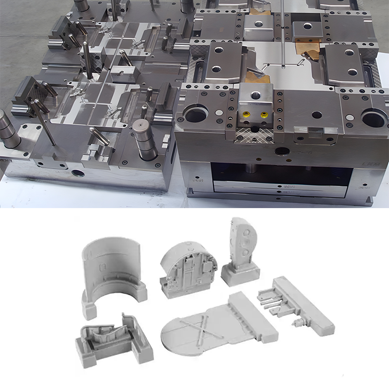
Flash on plastic parts mostly occur at the parting position of the mold, such as the parting surface of the mold, the sliding fit of the slider, the gap of the insert, and the hole of the ejector pin.
The Impact of Flash on Plastic Parts
The presence of flash can affect the quality and appearance of plastic parts, and may even impact their performance and lifespan. If these overflows are not resolved in time, they will further expand, imprinting the mold and causing localized subsidence, resulting in permanent damage. Flash in the insert gap and ejector pin hole can also cause the part to get stuck on the mold, affecting demolding. Therefore, measures need to be taken during the production of plastic parts to control and reduce the occurrence of flash.
Acceptance Standards for Flash on Plastic Parts
Strictly speaking, flash is inevitable, but most plastic overflow is negligible. Therefore, a certain standard needs to be set as a reference when accepting plastic parts. Generally, for products with high requirements, the flash should not exceed 0.05mm; for products with lower requirements, the flash should not exceed 0.1mm. The acceptance standard should be confirmed based on the actual use of the product.
Causes and Solutions for Flash In Injection Molding
1. Material Factors
Analysis:
① The plastic has too good flowability, and the melt viscosity is too low, making it prone to flash. For example, polyethylene (PE) and polypropylene (PP).
② The plastic raw material has uneven granularity, resulting in unstable feeding, leading to incomplete filling or flash.
③ Plastic raw materials with high water absorption decompose at high temperatures, reducing melt viscosity and causing flash, such as PA, ABS, PC, PMMA, etc.
Solution:
❶ Change the material or add additives to reduce flowability.
❷ Use materials with uniform granularity.
Material-related causes require product designers or mold practitioners to understand the characteristics of most materials. The table below shows the flowability of commonly used plastics:
| Material Name | Flowability |
|---|---|
| Polyethylene (PE) | 高 |
| 聚丙烯(PP) | 高 |
| Polystyrene (PS) | 高 |
| 丙烯腈-丁二烯-苯乙烯(ABS) | 中型 |
| Polyamide (PA) | 中型 |
| Polycarbonate (PC) | 中型 |
| Polyoxymethylene (POM) | 中型 |
| Polyethylene Terephthalate (PET) | 中型 |
| Polybutylene Terephthalate (PBT) | 中型 |
| Polyurethane (PU) | 中型 |
| Polyvinyl Chloride (PVC) | 低 |
| Polyvinylidene Chloride (PVDC) | 低 |
| Polyvinyl Acetate (PVA) | 低 |
| Polymethyl Methacrylate (PMMA) | 低 |
| Polypropylene Ethylene Copolymer (PPE) | 中型 |
| Polysulfone (PSU) | 中型 |
| Polyetheretherketone (PEEK) | 低 |
| Polydimethylsiloxane (PDMS) | 低 |
| Ethylene Vinyl Acetate (EVA) | 中型 |
| Thermoplastic Elastomer (TPE) | 高 |
2. Mold Factors
Analysis:
① The precision of the mold parting surface is poor.
The movable plate is deformed and warped, foreign matter is stuck on the parting surface, or there are protruding burrs around the mold base. The old mold has fatigue subsidence around the cavity due to previous flash squeezing.
② The mold design is unreasonable.
The cavity design is misaligned, causing tension on one side of the mold during injection, resulting in flash.
③ The mold has poor parallelism, is assembled non-parallel, the plate is non-parallel, or the tie rods have uneven force distribution and uneven deformation, all of which cause incomplete mold closure, resulting in flash.
④ The matching precision of the sliding core is poor, and the fixed core and cavity are misaligned, resulting in flash. In multi-cavity molds, if the runners and gates are not designed reasonably, uneven filling forces will also result in flash.
⑤ The number of gates is too few.
Solution:
❶ Improve processing precision and thicken the mold plate.
❷ Adjust product placement.
❸ Improve processing precision and increase mold testing precision; improve mold assembly precision, using red lead or blue lead fitting.
❹ Improve processing precision and increase mold testing precision; improve mold assembly precision, using red lead or blue lead fitting.
❺ Increase the number of gates or change their position.
The flash caused by this factor involves runner layout in mold design. For details, refer to the article “Mold Runner Design.”
This article will provide a brief introduction:
Reasonable runner design to solve flash problems
2.1 Strive for balance and symmetry
❶ All cavities should be filled simultaneously at the same temperature
a. Use a balanced layout

b. Non-balanced layout can achieve balance by adjusting the gate size

❷ Gate balance

❸ Symmetrical arrangement of large and small products

❹ Mold force balance, i.e., the injection pressure center coincides with the main runner center, to prevent flash.
2.2 Keep the runner as short as possible to reduce waste rate, molding cycle, and heat loss. The H-type layout is better than the ring or symmetrical type.
2.3 For high-precision products, the number of cavities should be as few as possible. Adding one cavity reduces product precision by 4%. The number of cavities for precision molds generally does not exceed 4.
2.4 Same color, same material.
2.5 Compact structure, saving steel materials
2.6 Big near, small far

2.7 Similar height
2.8 Large near, small far, fitting in gaps

2.9 For the same product, big near, small far

2.10 Good processability
3. Injection Process Factors
Analysis:
① Injection pressure too high or 注射速度 too fast. Due to high pressure and high speed, the opening force on the mold increases, leading to overflow.
② Overfeeding leads to flash.
③ The barrel, nozzle temperature too high or mold temperature too high can reduce plastic viscosity, increase flowability, and cause flash when flowing into the mold smoothly.
④ Holding time too long.
Solution:
❶ Reduce injection pressure and speed.
❷ Reduce material amount, weigh the weight in advance or gradually decrease during mold testing.
❸ Reduce the barrel, nozzle, mold temperature.
❹ Reduce holding time.
4. Injection Machine Factors
Analysis:
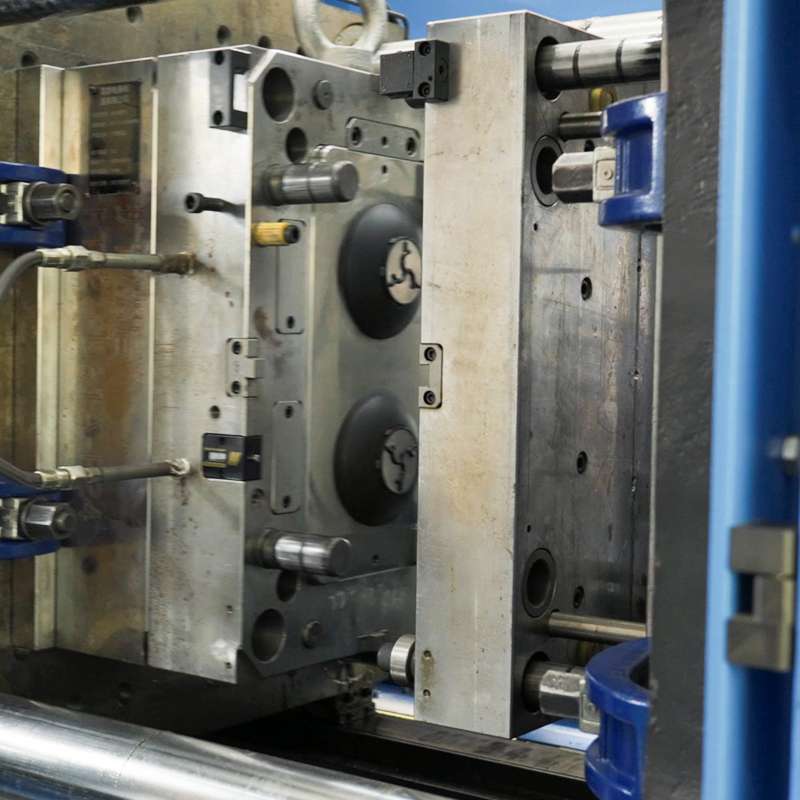
① Machine clamping force insufficient.
② Clamping device adjustment is poor, toggle mechanism not straightened, resulting in left, right, or top, bottom non-uniform clamping, mold parallelism poor causing one side tightly clamped and the other not, resulting in flash during injection.
③ The check ring worn severely, the spring of the spring nozzle failed, the barrel or screw worn excessively, cooling system failure at the feeding port, causing “bridging,” insufficient material feeding, and buffer pad too small, all may lead to recurring flash.
Solution:
❶ Replace with a larger tonnage injection machine.
❷ Check clamping, repair or replace in time if necessary.
❸ Replace injection parts.
A Typical Flash Case
Case Analysis – Router Housing Flash
The image below shows a housing product produced by a company using PC material. As observed, the flash is small and within acceptable limits. However, the customer, for certain reasons, requested to switch to PBT material. After switching materials, flash appeared, and it was challenging to resolve the issue through the process. Flash, also known as burrs, refers to the excess part on the edge of the product.
Reason Analysis and Improvement Measures
The flash in this case is mainly due to the product flash resulting from material replacement under the original molding process control.
Mold-Related Causes:
The product structure in this case is simple, using a single side gate injection point. The previous material used was PC, and the molding process settings and mold opening were according to PC material requirements. The overflow value (vent width) for PC material is 0.06mm, while that for PBT material is smaller at 0.02mm. Comparing the data, it is evident that if the mold is designed for 0.06mm, PBT will produce flash in areas where PC previously did not.
Measures to Solve the Above Problem:
During mold opening, adhere to the correct overflow value, otherwise, the mold needs to be modified.
Note: In this case, although PBT and PC materials differ in flowability and injection temperature, the difference in overflow value is a fact. Therefore, when replacing materials and designing molds, fully consider these impacts, as process adjustments may be challenging.
In Conclusion
Flash is one of the most common injection molding defects. An injection molding factory that can perfectly avoid or solve flash problems is a company with good process quality. Moreover, many plastic parts may encounter multiple issues simultaneously. Therefore, familiarity with structural design, mold design, sample testing, problem analysis and resolution, as well as ensuring appearance and material characteristics, are essential skills for every practitioner in the injection molding industry.
If you have any questions about flash, please feel free to contact us at [email protected].

