Plastic Product wall thickness is a critical structural feature frequently discussed and considered in the design of plastic product structures. It represents the thickness value between the outer and inner walls of a plastic part. The wall thickness is the basic parameter that determines the overall thickness of the product and is often specified during the structural design process.
Understanding the significance of wall thickness characteristics is crucial in the structural design of plastic products during mold design and the injection molding process, as it plays an important role in producing plastic items using the widely utilized injection molding method.
The outer wall of the shell part functions as the outer skin, while the inner wall acts as the structural skeleton. We can apply surface treatment to the outer wall to achieve different appearance effects. Other structures within the part, such as tendons, screws, and buckles, are connected to create strength and can be filled during injection molding. Without special requirements like heat dissipation or assembly, the inner and outer walls are typically designed as a unified whole to provide sufficient strength and protect internal parts.
For the internal parts, which often serve as bearings or connecting brackets, there are fewer strict requirements for the inner and outer walls. Based on the specific situation of the inner or outer wall, we can create structures such as reinforcements, screws, or buckles. However, in order to facilitate production and manufacturing, the outer wall is generally designed to be as simple as possible. If necessary, we can adjust to the draft angle of the cavity and core or implement designs such as ejector pins in the cavity or buckles in the core.
In both shell parts and internal parts, the wall thickness plays a crucial role in providing an ejection surface for the ejector pins, ensuring smooth ejection of the part from the mold.
Design principles for wall thickness of plastic products
In the structural design of plastic parts, the wall thickness is a critical parameter that serves as the foundation for the design. Other structures are created based on the chosen wall thickness. The wall thickness significantly affects the plastic parts’ mechanical properties, formability, appearance, and cost. Therefore, the wall thickness should be carefully considered and designed in accordance with these factors.
Regarding the meaning of wall thickness, it is mentioned that it should have a specific value. If there is only one value, it indicates a uniform wall thickness throughout the part. However, if there are multiple values, it suggests that the wall thickness is not uniform and different sections of the part have varying thicknesses. We should strive to comprehend the principles of wall thickness design to ensure the plastic part’s optimal performance and functionality.
Based on the principle of mechanical performance
As discussed earlier concerning wall thickness, it is crucial for both shell and internal parts to possess sufficient strength. The ability to withstand the release force during molding is a crucial factor to consider. Typically, excessively thin parts are prone to deformation upon ejection. Generally, increasing the wall thickness enhances the part’s strength (with approximately a 33% strength increase for every 10% increase in wall thickness). However, exceeding a certain wall thickness range can result in quality issues like sink marks and porosity, diminishing the part’s strength while increasing its weight.
Consequently, this leads to longer injection molding cycles and higher material costs. Solely relying on increased wall thickness for strengthening plastic parts is not the most optimal solution. Instead, it is advisable to employ geometric features such as ribs, curves, corrugated surfaces, and reinforcements to enhance stiffness.
In situations where space and other factors do not allow for alternative approaches, the part’s strength is predominantly achieved through the appropriate wall thickness. In such cases, if strength is a critical consideration, it is recommended to determine the suitable wall thickness through mechanical simulation while adhering to the fundamental principles of formability.
Based on the principle of injection moldability
In fact, the wall thickness is the thickness of the cavity formed by the core and cavity. The wall thickness is formed when the molten resin fills the cavity and cools to form the part.
1) How does the molten resin flow during the injection filling process?
In injection molding, we can often approximate the flow of plastic in the mold cavity as laminar flow. Laminar flow refers to the smooth, orderly movement of layers of liquid adjacent to each other, with minimal mixing or turbulence. According to fluid mechanics principles, laminar flow occurs when the layers of liquid slip relative to each other under the influence of shear stress. Shear stress is the force that causes the material to deform and slide along a plane parallel to the acting force, which is also known as tangential stress. It’s important to note that while laminar flow is a common approximation, in certain cases, such as when dealing with high flow rates or complex geometries, the flow behavior may deviate from laminar flow and exhibit turbulent characteristics.

During the injection molding process, when the molten resin flows into the mold cavity, it comes into contact with the runner or mold cavity walls. The layer of molten resin is adjacent to the runner wall or mold cavity wall experiences cooling and begins to solidify. This solidification creates frictional resistance to the liquid resin layer adjacent to it. Consequently, the middle layer of the molten resin, being furthest from the solidifying walls, generally exhibits the highest velocity. The velocity of the layers near the runner wall or mold cavity wall gradually decreases due to the frictional resistance and the solidification process. This velocity distribution across the flow front is commonly observed in injection molding and contributes to the overall flow behavior of the molten resin during the filling stage.
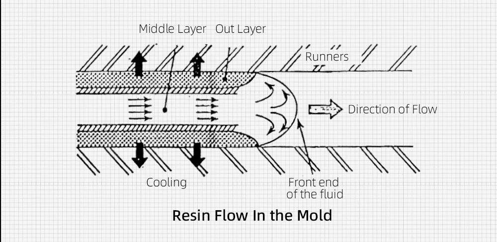
As depicted in the figure mentioned, the middle layer is the flow layer, while the outer layer is the curing layer. The curing layer gradually thickens as the molten resin cools and solidifies over time. This thickening of the curing layer reduces the cross-sectional area available for the flow layer, making it more challenging to fill the mold cavity.
To effectively compensate for this, we need to increase the injection pressure to push the molten resin into the mold cavity and complete the filling process.
As a result, the wall thickness of injection molded parts significantly impacts the flow and filling stages of the injection process. It is crucial to ensure that the wall thickness is not too small, as this can impede the flow and filling of the molten resin. Therefore, appropriate wall thickness is essential for successful injection molding and proper part formation.
(2) the viscosity of the plastic melt also has a significant impact on the fluidity
When external forces, such as shear stress, exert upon a fluid, the layers of the fluid undergo relative motion, leading to the development of internal friction, which is referred to as viscosity.
Parameters such as dynamic viscosity or viscosity coefficient can quantify viscosity by considering the shear stress exerted on the fluid and the resulting shear rate.
Melt viscosity is a crucial characteristic that reflects the flow behavior of molten plastic. It measures the resistance to flow exhibited by the melt. Higher viscosity corresponds to more excellent resistance, making the flow more difficult. Melt viscosity depends not only on the molecular structure of the plastic but also on factors such as temperature, pressure, shear rate, and the presence of additives. These factors can influence the flow properties of the molten plastic during injection molding.
In practical applications, we commonly use the melt index to characterize the fluidity of plastic materials during processing. A higher melt index value indicates better fluidity of the plastic material, making it easier to flow and fill the mold cavity. Conversely, a lower melt index value suggests lower fluidity, making the flow more challenging.
Based on mold design requirements, we can categorize the fluidity of commonly used plastics into three general groups:
Good fluidity: Plastics such as PA (nylon), PE (polyethylene), PS (polystyrene), PP (polypropylene), CA (cellulose acetate), and poly(4) methyl pentene exhibit good fluidity during the injection molding process.
Medium fluidity: Polystyrene series resins (such as ABS and AS), PMMA (polymethyl methacrylate), POM (polyoxymethylene or acetal), and PPO (polyphenylene oxide) possess medium fluidity characteristics.
Poor fluidity: Plastics like PC (polycarbonate), rigid PVC (polyvinyl chloride), PPO (polyphenylene oxide), PSF (polysulfone), PASF, and fluoroplastics exhibit poor fluidity during processing.
These categorizations provide a general guideline for selecting plastics with suitable fluidity characteristics based on the complexity and requirements of the injection molded parts.
| Resin | Minimum Wall Thickness | Recommended Wall Thickness For Small Plastic Products | Recommended Wall Thickness For Medium Plastic Products | Recommended Wall Thickness For Large Plastic Products |
|---|---|---|---|---|
| PA | 0.45 | 0.75 | 1.6 | 2.4~3.2 |
| PE | 0.6 | 1.25 | 1.6 | 2.4~3.2 |
| PS | 0.75 | 1.25 | 1.6 | 3.2~5.4 |
| HIPS | 0.75 | 1.25 | 1.6 | 3.2~5.4 |
| PMMA | 0.8 | 1.5 | 2.2 | 4~6.5 |
| PVC | 1.15 | 1.6 | 1.8 | 3.2~5.8 |
| PP | 0.8 | 1.45 | 1.75 | 2.4~3.2 |
| PC | 0.95 | 1.8 | 2.3 | 3~4.5 |
| PPO | 1.2 | 1.75 | 2.5 | 3.5~6.4 |
| EC | 0.7 | 1.25 | 1.9 | 3.2~4.8 |
| POM | 0.8 | 1.4 | 1.6 | 3.2~5.4 |
| PSF | 0.95 | 1.8 | 2.3 | 3~4.5 |
| ABS | 0.75 | 1.5 | 2 | 3~3.5 |
The wall thickness of plastic parts can be selected according to the different materials and the size of the product form factor. The range is generally 0.6 ~ 6.0mm, and the common thickness is generally between 1.5 ~ and 3.0mm. The following are the recommended wall thickness values for different materials: (The wall thickness of internal load-bearing parts can be increased based on the following chart)
3) Wall thickness calculation by means of the flow path to thickness ratio
The flow ratio (L/T) of plastic refers to the ratio of the flow path length (L) to the wall thickness (T). It represents the relationship between the flow distance and the wall thickness in plastic injection molding.
A larger L/T ratio indicates that the plastic melt will flow further within the mold cavity for a given wall thickness. Conversely, for a given desired flow path, a larger L/T ratio allows for a smaller wall thickness. Therefore, the L/T ratio of plastic directly impacts the number and distribution of injection points in plastic products and the achievable wall thickness.
Various factors, including material temperature, mold temperature, surface finish, and other conditions, influence the calculation of the L/T ratio. The value provided is an approximate range and can vary depending on specific circumstances. While it serves as a practical reference value, precise calculations may be challenging due to the complexity and variability of injection molding processes. It is advisable to consider these factors and seek guidance from experienced professionals to determine the wall thickness in specific cases accurately.
| Resin | L/T Ratio |
|---|---|
| LDPE | 270 |
| HDPE | 230 |
| PE | 250 |
| PP | 250 |
| PS | 210 |
| ABS | 190 |
| PC | 90 |
| PA | 170 |
| POM | 150 |
| PMMA | 130 |
| HPVC | 100 |
| SPVC | 100 |
Calculation Start
For example, if we have a plastic part made of PC material with a product wall thickness of 2mm, a product filling distance of 200mm, a runner length of 100mm, and a runner diameter of 5mm, we can calculate the L/T ratio.
L/T (total) = L1/T1 (sprue) + L2/T2 (runner) + L3/T3 (product) = 100/5 + 200/2 = 120.

In this case, the calculated L/T ratio is 120, which exceeds the reference value of 90 for PC material. This indicates that the injection molding process may encounter difficulties achieving proper filling. To tackle this issue, we may need to enhance the injection rate and pressure or explore utilizing specialized high-performance injection molding equipment.
To improve moldability, one can reduce the product filling distance by changing the gate position or using multiple gates. For example, if the product filling distance is reduced to 100mm, the new L/T ratio becomes 70, less than the reference value. It would make the injection molding process easier.
Alternatively, adjusting the product’s wall thickness can also impact the L/T ratio. If we change the wall thickness to 3mm, the new L/T ratio will be 87, closer to the reference value, indicating that we can successfully execute the injection molding process.
Based on the principle of appearance
The wall thickness affects the appearance of the parts, specifically as follows.
(1) uneven wall thickness: Sink mark, deflection, etc.
(2) wall thickness is too large: sink mark, void, etc.
(3) wall thickness is too small: short shot, ejector marks, deflection, etc.
However, many product structure designers discover defects only after the mold trial. At that point, they typically rely on the mold factory to address the issues by adjusting injection parameters during the molding process. While this approach can be relatively fast and cost-effective, it is only sometimes guaranteed to be effective. Therefore, conducting a thorough Design for Manufacturability (DFM) analysis before the design phase is crucial. Approximately 70% of injection molding defects occur during the structural and mold design stages. By performing a thorough DFM analysis at an early stage, we can identify and address potential issues proactively, leading to improved manufacturing outcomes and minimizing the need for modifications after the trial phase.
Based on cost principles
Among the various stages in the injection molding process, the cooling time is typically the longest and most critical factor affecting the overall molding cycle of a product.
After we inject the molten plastic into the mold cavity, it is necessary to provide adequate time for cooling and solidification before we can open the mold and eject the part. The cooling time is influenced by material properties, part geometry, wall thickness, mold design, and cooling system efficiency.
Increasing the wall thickness of the part beyond the necessary requirements can result in longer cooling times. This extended cooling time can significantly impact the molding cycle, reducing productivity and increasing costs per part. Manufacturers aim to optimize the cooling time by considering the desired part quality, cycle time, and production efficiency.
Designers and engineers need to balance part functionality, structural integrity, and cooling requirements to minimize the cooling time while ensuring the desired quality of the final product. This optimization can help improve productivity and cost-effectiveness in the injection molding process.
In Summary
The above design principles of the wall thickness of injection molded parts are detailed from four aspects: mechanical properties, injection moldability, appearance, and cost. In summary, the goal is to design the wall thickness to meet the required mechanical properties, optimize processing performance by minimizing the thickness, ensure uniformity where possible, and incorporate smooth and gradual transitions where necessary.