The draft angle is not exclusive to injection molding. Its importance resonates across various process technologies. For example, in injection molding, the draft angle is crucial for facilitating the smooth ejection of parts without causing damage. Similarly, in die casting, the draft angle prevents castings from locking into the mold. By ensuring that the mold and molded parts are not perfectly parallel, the draft angle provides a slight taper that makes it easier to remove the parts. This concept extends to most manufacturing processes involving molds, highlighting its universal importance.
Today, let’s discuss this important concept.

Meaning of Draft Angle
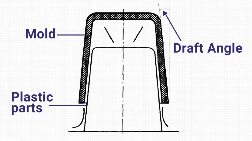
The term draft angle refers to the angle designed into the mold to facilitate the removal of the molded part. Specifically, it is the angle of the molded surfaces in the direction of mold opening.
Who Designs the Draft Angle?
Since the draft angle is ultimately reflected in the mold, there is often debate over whether the draft angle should be designed by the structural engineer or the mold engineer. Currently, there are two main approaches:
- The structural engineer should ensure that all surfaces have a draft angle during the part design stage (except for some structures that require mold engineer evaluation).
- The structural engineer is responsible for applying draft angles to appearance surfaces and key assembly surfaces, while other non-critical surfaces are left to the mold engineer to handle during mold design based on experience.
Both approaches have their pros and cons, and the choice should be made based on the specific situation:
For the first approach:
Pros:
- Ensures no structural interference, maintains design requirements for assembly gaps, and dimensional tolerances, thus guaranteeing part quality.
- Saves time in mold DFM (Design for Manufacturability) review, avoiding subsequent quality disputes.
Cons:
- Requires the structural engineer to have extensive mold-related experience; otherwise, the designed draft angles might not facilitate smooth ejection.
- Since all surfaces need a draft angle, the structural engineer’s workload increases, potentially delaying projects with tight timelines.
- The original vertical surfaces become sloped after applying draft angles, complicating subsequent structural modifications.
- The addition of draft angles results in more interference lines in engineering drawings, increasing the likelihood of annotation errors.
For the second approach:
Pros:
- Saves design time for the structural engineer; experienced mold engineers design the draft angles, usually ensuring smooth ejection.
- Simplifies subsequent structural modifications and engineering drawing annotations for the structural engineer.
Cons:
- Mold engineers may not fully understand the product’s functional requirements, thinking only from an ejection perspective, possibly failing to meet structural requirements such as interference, gaps, dimensions, and strength.
- Increases the mold engineer’s workload, as they typically remove the fillets before adding the draft angle, then reapply the fillets, potentially resulting in discrepancies between the new and original fillets.
Types of Draft Angles
Draft angles can be classified into cavity draft angles and core draft angles, distinguished by the parting line that separates the cavity and core. The surfaces parallel to the ejection direction in the cavity require core draft angles, and those in the core require core draft angles. Additionally, if the mold has side cores (lifters and sliders), these require lifter draft angles and slider draft angles, with the draft direction following the movement direction of the slider.
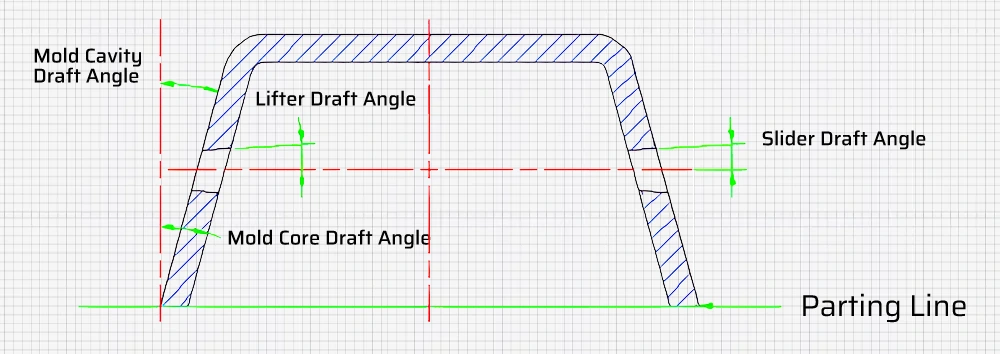
The draft direction is generally based on the parting line to ensure that the larger dimension after drafting is near the parting line, facilitating smooth ejection.
Why Design Draft Angles?
Draft angles are a process structure. Theoretically, product structures do not need draft angles unless required by the design. However, due to the limitations of molding processes like injection molding, plastic products need to be removed from the mold after molding and cooling. Without draft angles, it would be very difficult to remove plastic parts from the mold. Think about the difficulty of separating stacked plastic stools, which already have a draft angle, let alone plastic parts without draft angles needing removal from the mold.
Why is it difficult to remove plastic parts from the mold without a draft angle?
In injection molding, the molten resin flows into the closed mold and fills the cavity between the core and the cavity. Thermoplastic materials tend to shrink toward the mold core during cooling, causing the plastic parts to adhere tightly to the mold core. Additionally, some plastics may pull away from the mold cavity wall microscopically, but most will still contact the cavity wall.
During mold opening, whether the outer surface of the plastic part contacts the cavity wall or the inner surface contacts the core, the plastic part experiences a frictional resistance opposite to the direction of ejection. The frictional force, represented by 𝑓=𝜇×𝐹𝑛f=μ×Fn, depends on the roughness of the contact surface (𝜇μ) and the shrinkage stress (𝐹𝑛Fn), which in turn relates to the draft angle.
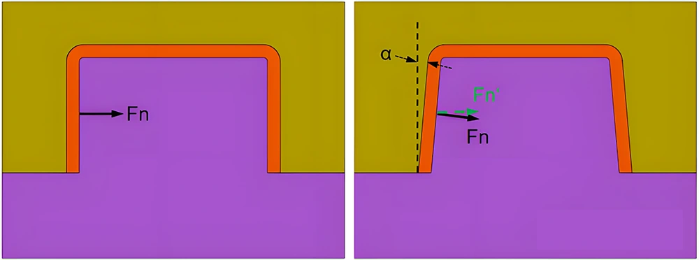
By designing a draft angle, the frictional force in the ejection direction 𝑓=𝜇×𝐹𝑛×cos𝛼f=μ×Fn×cosα decreases as the draft angle 𝛼α increases. Generally, the draft angle is not very large, so its contribution to reducing static friction is limited.
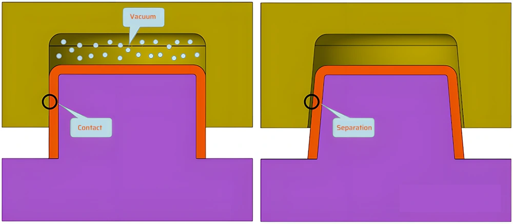
The main function of the draft angle is to ensure that once the plastic part separates from the mold, it no longer contacts the mold, eliminating friction. Without a draft angle, the plastic part would transition to sliding friction upon separation, and for high-gloss surfaces, the cavity might form a vacuum, making it difficult to completely separate the plastic part from the cavity. The worst-case scenario is sticking to the cavity, causing deformation of the plastic part’s core structure during ejection.
Benefits of Draft Angles:
Draft angles can sometimes create conflicts of interest. Injection molders prefer larger draft angles for easier ejection. Mold manufacturers, on the other hand, find machining all cavity and core surfaces with angles a challenging task, as it complicates simple features that could otherwise be machined with simpler equipment and lower costs. Product designers may find that draft angles complicate part design and alter the appearance.
Despite these challenges, ensuring molded parts meet required quality standards is crucial. Without draft angles, the chances of injection molding issues increase, unnecessarily raising production costs and extending delivery times. Apart from facilitating part removal from the mold, draft angles offer other benefits:
- Reduce the possibility of damaging part surfaces during ejection.
- Ensure uniformity and integrity of surface textures and finishes.
- Minimize part deformation due to ejection resistance.
- Reduce wear on molded parts and decrease the likelihood of mold damage.
- Shorten overall cooling time by eliminating or reducing the need for complex ejection setups.
- Directly and indirectly lower overall production costs.
Principles of Draft Angle Design
- Ensure Smooth Ejection
- Maintain Structural Functionality
- Meet Aesthetic Requirements
Ensuring Smooth Ejection:
After the mold opens, the plastic part should remain on the core side to facilitate final ejection.
Removing a plastic part from the mold involves two steps:
1. Separates from the cavity wall
The outer surface of the plastic part separates from the cavity wall. Typically, there are no additional structures aiding this separation, so the friction between the outer surface and the cavity wall should be minimized.
2. Separates from the core wall
The inner surface of the plastic part separates from the core wall. The mold generally uses ejector pins, angled pins, or ejector plates for this. The friction between the inner surface and the core should be greater than that between the outer surface and the cavity wall to ensure the part stays on the core side during mold opening.
Since plastic tends to shrink toward the mold core, creating greater shrinkage stress, the friction between the inner surface and the core will be higher than that between the outer surface and the cavity wall, given consistent roughness and draft angle. This is why cores are usually designed into the core, and cavities into the cavity, with the complex side of the plastic part in the core and the relatively simple side (appearance side) in the cavity.
However, there are exceptions. For instance, if the inner surface is an appearance surface that cannot have ejector pin marks, the core would be in the cavity, and the cavity in the core. To prevent sticking to the cavity, the cavity needs auxiliary ejection mechanisms.
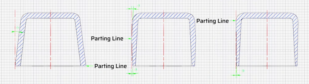
In some cases, parts may have similar top and bottom surfaces with no distinct appearance side. For these parts, if there are no specific requirements, the core’s draft angle should be minimized while the cavity’s draft angle should be maximized (within part tolerance) to ensure the part remains on the moving mold side, avoiding the need for auxiliary ejection mechanisms in the cavity.
For structures with adjustable design, the core can be modified so that 1/3 is in the cavity and 2/3 in the core, reducing the risk of sticking to the cavity.
Determining the Draft Angle Size:
There is no unified standard for the draft angle size, and theoretical calculations are challenging due to the complexity of friction models and varying injection parameters. Simulation can provide reference values, but it is time-consuming and resource-intensive, often beyond the capabilities of mold shops. Practical experience is crucial, and structural engineers need to understand this aspect to incorporate draft angles into critical structures during design, reducing the need for subsequent modifications based on mold engineer feedback and avoiding unnecessary issues.
Factors influencing draft angle size:
- Material Characteristics: Hard plastics require larger draft angles than soft plastics, which may not need draft angles at all due to their flexibility.
- Shrinkage Rate: Plastics with higher shrinkage rates grip the core more tightly, requiring larger draft angles.
- Friction Coefficient: Materials with lower friction coefficients, such as PA and POM, need smaller draft angles. Rougher surfaces require larger draft angles.
- Wall Thickness: Thicker walls exert greater force on the core, necessitating larger draft angles.
- Geometric Complexity: Complex shapes or parts with many holes require larger draft angles to avoid needing numerous ejector pins, which must be symmetrically arranged to prevent warping during ejection.
- Transparency: Parts with optical requirements need larger draft angles.
Specific Draft Angle Ranges:
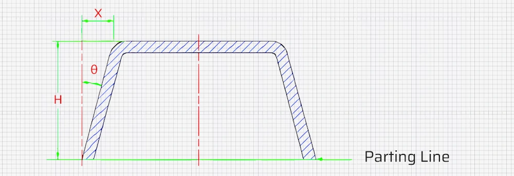
The geometric relationship for draft angles is tan𝜃=𝑋𝐻tanθ=HX, where 𝜃θ is the draft angle, 𝐻H is the height of the drafted surface, and 𝑋X is the reduced wall thickness or taper.
Theoretically, larger draft angles facilitate easier ejection, especially for tall (deep) and large-surface areas that grip the core or cavity tightly, requiring larger angles for smooth ejection.
However, a larger 𝜃θ means a greater 𝑋X, which affects the design:
1. For appearance surfaces
A larger 𝑋X significantly alters the design, potentially deviating from the intended look. Therefore, the draft angle should be as large as permissible. If not, consider the following:
- High-gloss surfaces require at least a 1° draft to prevent scratching; larger values are preferred if possible.
- Textured surfaces require at least a 3° draft, depending on texture type and depth. Generally, 0.001 mm depth requires 1° to 1.5° of draft.
- Straight surfaces need a draft considering parting lines, to be discussed in a subsequent section.
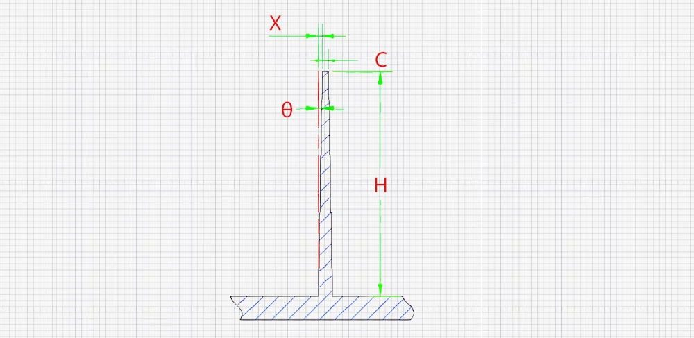
2. For rib surfaces
A larger 𝑋X reduces the top width 𝐶C, making injection molding more difficult. Ribs should be designed shorter, allowing for larger draft angles. If unavoidable, ensure 𝑋≥0.2X≥0.2 and 𝐶≥0.6C≥0.6.
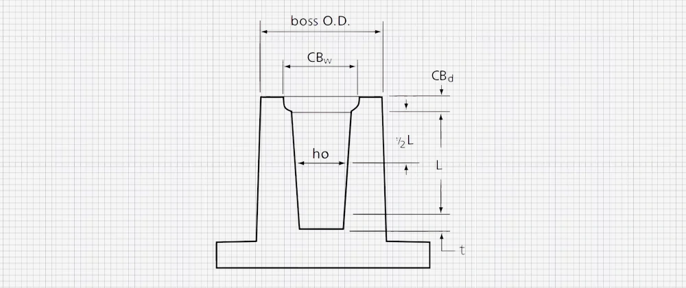
3. For screw bosses
The inner hole requires dimensional accuracy. The draft angle is small or zero, necessitating low roughness or polishing and appropriate ejector pin placement. Using core pins for ejection avoids the need for a draft angle, while ordinary ejector pins require a draft angle. The height of screw bosses should not be excessive, with angles between 0.5° and 1.0°. Draft should be based on half the thread engagement depth 𝐿L to ensure proper screw fit, avoiding loose fit at the top and tight fit at the bottom, which introduces stress.
4. Other internal surfaces use a draft angle of 1° as a baseline, adjusted based on height and roughness, considering changes in wall thickness to avoid molding defects.
Ensuring Structural Functionality:
A complete product is composed of different parts connected to form a whole. The draft angle of one part affects itself and the other parts it connects with.
1. Impact on screw support surfaces:
Applying a draft angle facilitates ejection but causes the support surface to be non-perpendicular to the screw axis, potentially tilting the fixed part when tightened.
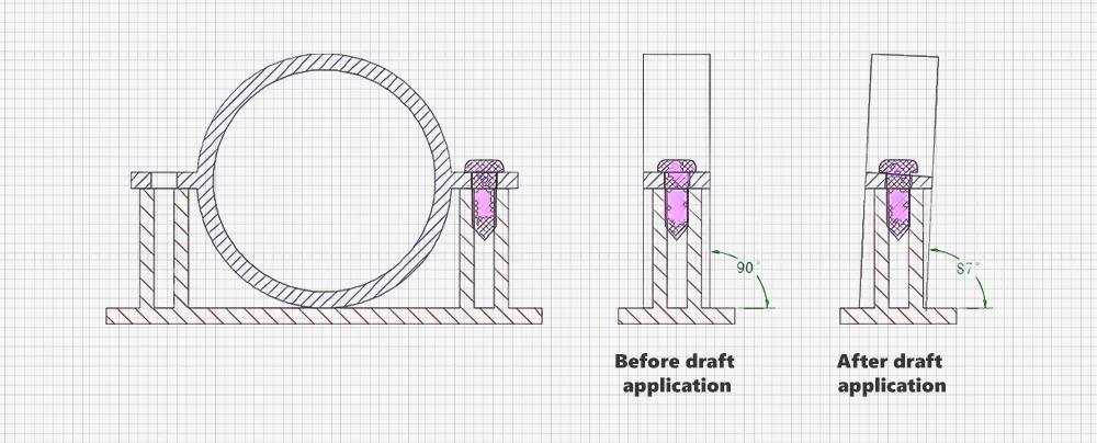
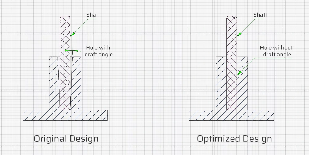
2. Impact on interference fits:
Plastic parts with matching drafts maintain interference fit accuracy. However, standard parts (e.g., bearings, shafts) without draft angles need careful consideration. For example, a small shaft interference fit with a column bore loses effectiveness if the bore has a draft angle. Using a core pin for ejection maintains the bore without a draft angle.
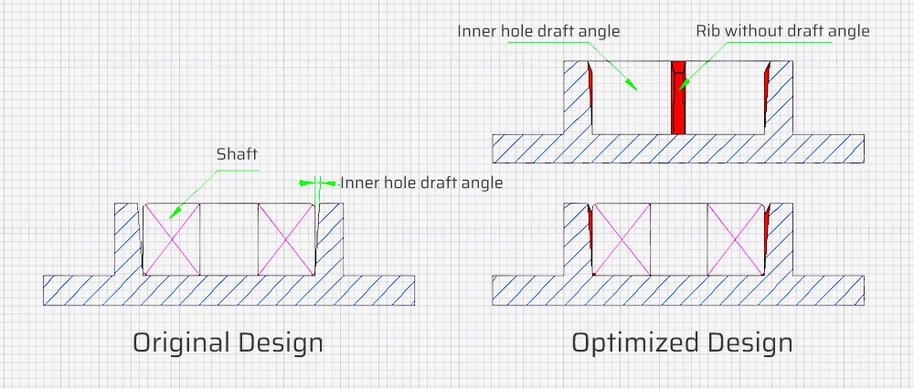
For bearing interference fits, large bore diameters can’t achieve a zero draft angle with core pins. Conventional ejection requires a draft angle. For instance, large bearing bores need an internal draft angle, while rib surfaces with small areas may not need a draft angle, allowing forced ejection.
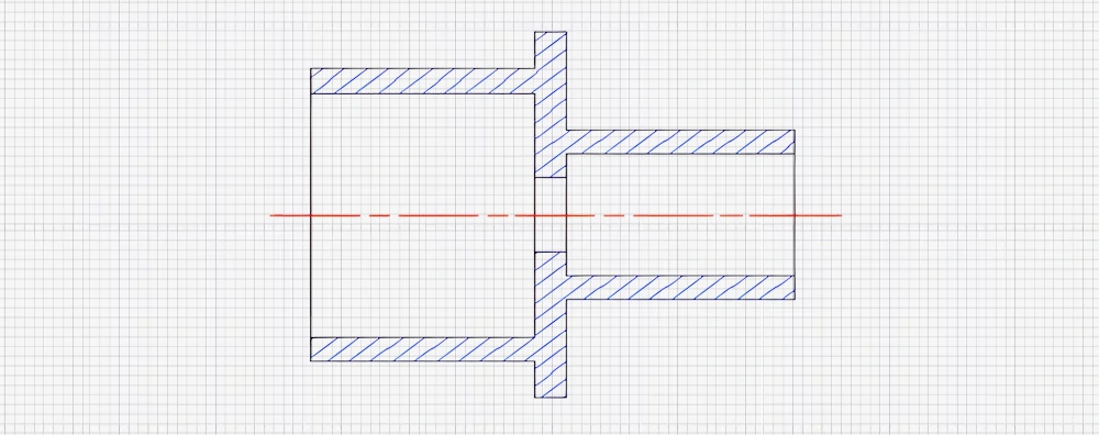
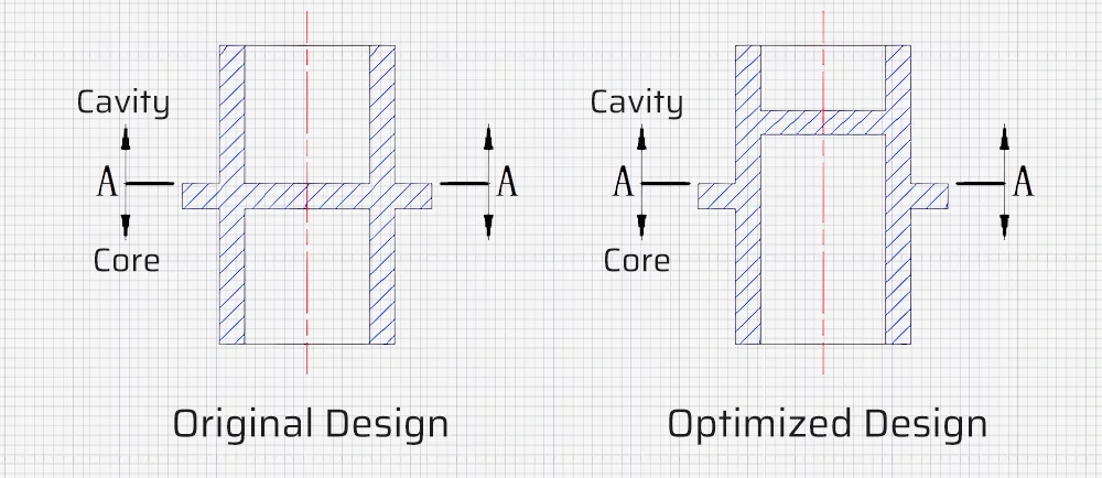
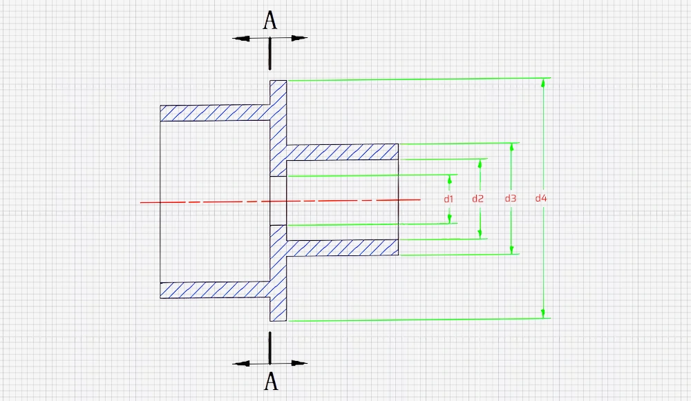
3. Concentricity requirements:
When there are concentricity requirements for features like d1, d2, d3, and d4, the parting line must be at A-A, with d1 and d2 on the same core to ensure mold accuracy.
4. Effect on appearance and structure of parting lines:
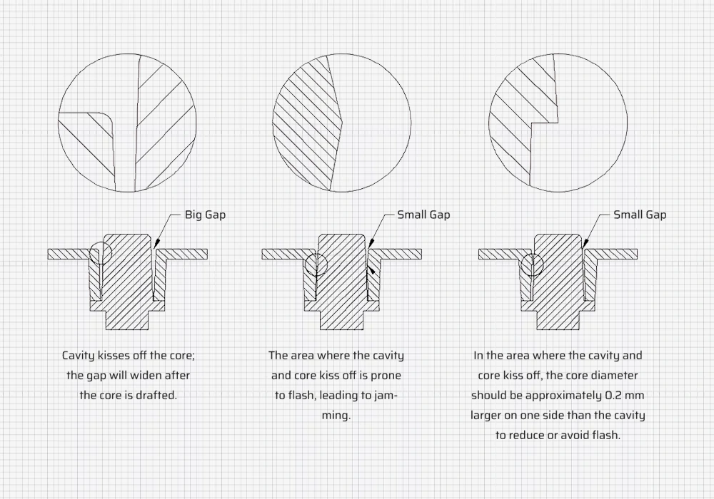
Common through-holes are formed by cavity and core contact at different points, creating parting lines. Drafting the through-hole presents three kiss-off methods, generating parting lines where the cavity and core meet.
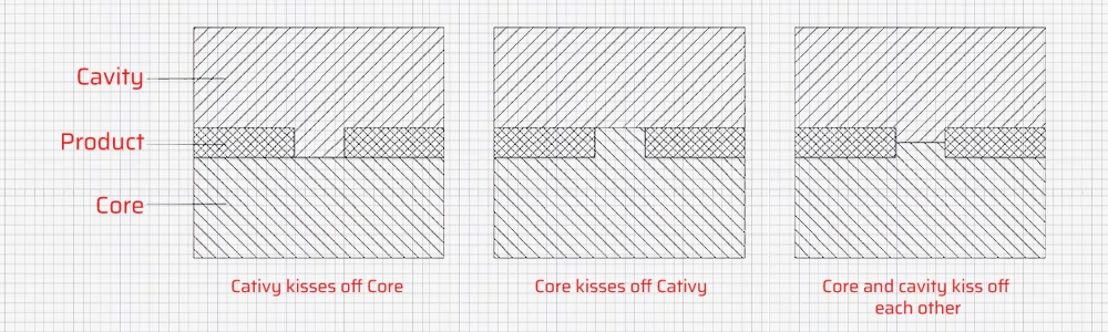
Cavity kisses off core:
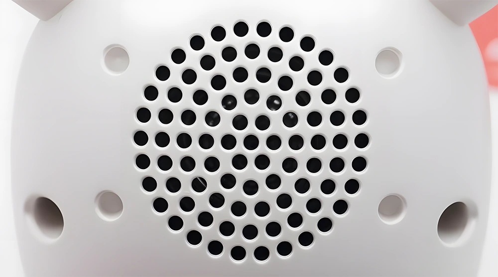
The inner wall of the hole, after drafting, remains in the cavity. This method is commonly used for appearance feature holes such as ventilation holes, speaker holes, and external interface holes. These holes generally do not allow the parting line or flash to be visible on the exterior surface and usually require chamfers, making this method the preferred choice. However, it is important to note that this method carries a risk of sticking to the cavity, especially when there are many holes, such as ventilation or speaker holes. Therefore, if the core does not have sufficient structure to ensure that the part stays on the core when separating the core and cavit, it is advisable to use a “kiss off each other”, where the cavity’s depth is less than the core’s depth.
Core kisses off cavity:
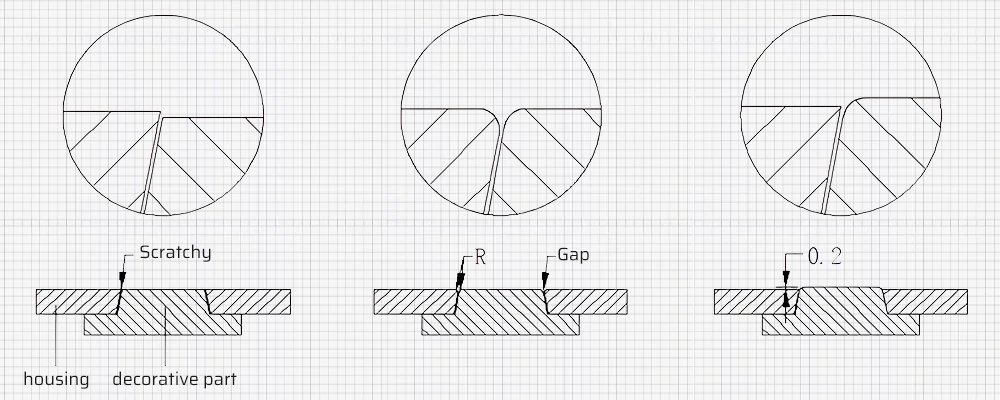
The inner wall of the hole, after drafting, remains in the core. This method is generally used for holes that do not appear alone because the parting line (flash) is on the exterior surface. These holes are typically used in conjunction with other parts, such as having a decorative piece fitted in the middle of the hole.
Since the flash of holes formed this way is on the exterior surface, if the decorative piece is flush with the casing, any errors (due to low mold precision or unstable structure) may cause them to not be truly flush, resulting in a step that can scratch hands. If both parts are chamfered at the R-angle on the exterior, it will not scratch hands, but the gap will appear larger. If only the decorative piece is chamfered at the R-angle and its surface is about 0.2 mm higher than the casing surface, it will not scratch hands and the gap will not appear larger.
Core and cavity kisses off each other:
The inner wall of the hole, after drafting, remains in both the core and cavity. This method is used not only to address the risk of sticking to the cavity, as mentioned earlier, but also in situations where the hole is quite deep. After drafting, the diameters of the upper and lower ends of the hole can differ significantly. To avoid this, the core and cavity are typically used to form the hole, which is commonly applied in button structures, as shown in the diagram below.
Ensuring Aesthetic Requirements:
Whether appearance parts require draft angles mainly depends on the disassembly method of the appearance parts and the corresponding ejection method. Designers with strict appearance requirements will consider the design state and general disassembly method in the early design stages. This is because when structural engineers add draft angles to the appearance later on, it will affect the appearance to some extent.
Of course, this impact needs to be acknowledged by the appearance designer before proceeding to the next step. Otherwise, the structural engineer must consider other ejection methods while preserving the original appearance. This process involves constant communication and cooperation between structural engineers and appearance designers. Different companies may place varying emphasis on structure and appearance, leading to differences in product quality and cost.

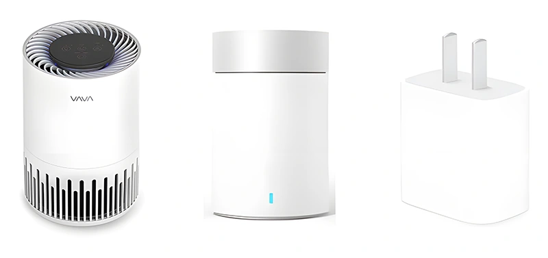
The images above illustrate the evolution of typical shaver main body designs:
First Design:
This is an early design with an upper and lower shell. The parting line between the upper and lower shells requires draft angles. After applying the draft angles, the joint between the upper and lower shells changes slightly and is no longer tangential, so decorative lines are often added here to reduce sharp edges that might cause discomfort.
Second Design:
To address the issues of the first design, a middle shell was added, which also serves as a decorative element. This significantly enhances the overall appearance but adds the cost of an additional part.
Third Design:
This is a minimalist style with a single-piece main body and a cylindrical appearance. It has no draft angles on the sides and no gaps, completely preserving the original design. This is a popular current design approach.
Similar trends apply to hairdryers, moving from traditional to modern, simpler designs with fewer parts and less impact on appearance from draft angles.

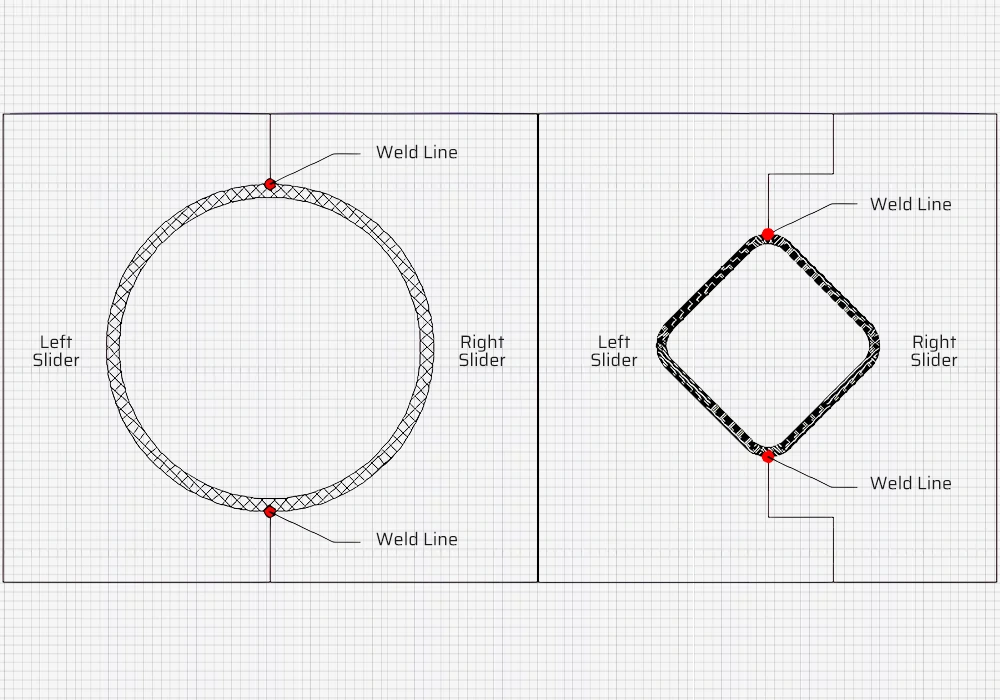
Zero Draft Angle Molds:
Some cylindrical appearance products avoid draft angles to maintain aesthetics. If the shell is metal, aluminum extrusion allows for zero draft angle on inner and outer walls. For plastic parts, the inner wall still needs a draft angle, with the outer wall molded using side sliders, leaving parting lines that can be polished and painted to conceal them.
Apple Pencil 1st Generation Zero Draft Angle:
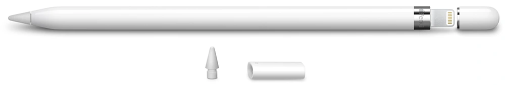
The 1st generation Apple Pencil’s barrel is made of plastic and features a long section with zero draft angle on both the inner and outer walls. While the solutions mentioned earlier can be used for ejecting the outer wall with zero draft angle, ejecting the inner wall with zero draft angle is more challenging.
According to a patent filed by Apple, the solution involves using a flexible mold core composed of two parts: a flexible slotted metal sleeve (FIG. 3) and a metal inner core (FIG. 5). This flexible sleeve can elastically deform under certain conditions, allowing it to be withdrawn from the cylindrical cavity of the Apple Pencil.
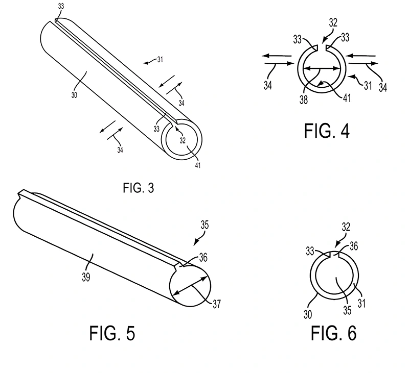
Specific Implementation:
The metal sleeve is made of low-friction metal and polished on the outer surface to reduce friction with the plastic. The sleeve has a continuous slot, providing it with elastic deformation space. The corresponding metal inner core has a raised key, and together they form the mold core (FIG. 6).
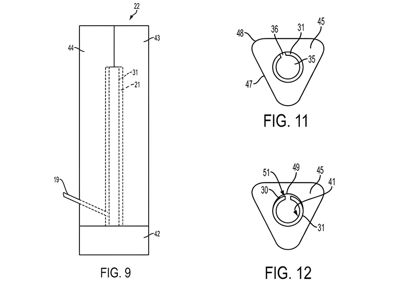
During the injection process, the mold core is first placed inside the mold, and then the outer mold is closed (FIG. 9) to complete the injection molding. After molding, the metal inner core is first removed, creating space for the flexible sleeve to elastically deform inward. This inward contraction causes the metal sleeve to detach from the inner wall of the plastic part to some extent, making it easy to withdraw the sleeve from the plastic part’s inner wall (the patent uses a triangular prism example to illustrate the cylindrical plastic barrel of the Apple Pencil).
Summary:
Finally, we once again emphasize the importance of the draft angle. Proper draft angle design has a crucial impact on product quality and production efficiency. By understanding the effects of draft angles on products and how to correctly apply them in mold design, we can improve mold design work, enhance product quality, and increase production efficiency.