While we have previously covered the topics of sprue and runner in detail, today, our focus will be on understanding the significance of the gate—the crucial junction where the plastic melt enters the mold cavity. The gate is one of the more challenging and complex structures in the entire feeding system, hoping this article will be helpful.
To aid in a better understanding of the gate, let’s review the knowledge covered in previous articles.
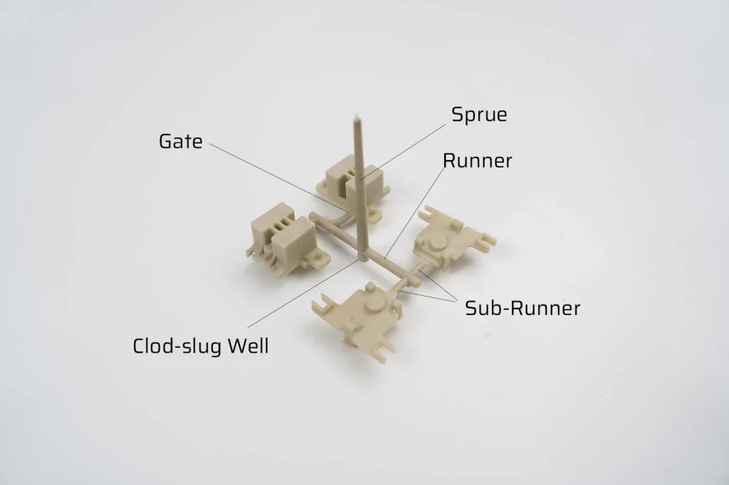
The feeding system refers to the channels through which molten plastic passes from the injection machine’s nozzle to the mold cavity. The sequential structures through which molten plastic passes are the sprue, runner, sub-runner, and gate. It’s evident that the gate is the final checkpoint before the liquid plastic enters the mold cavity.
Due to its role in connecting the cavity and the feeding system, the choice of gate location is exceptionally crucial. Some even say that the success of mold design is directly related to the selection of gate location.
Types of Injection Molding Gate
Gates are commonly categorized into two types: restrictive gates and non-restrictive gates. Restrictive gates typically refer to sprue gates, which have a narrow opening that restricts the flow of molten material. On the other hand, non-restrictive gates encompass a broader range of gate types with more design options.

Direct Gate/Sprue Gate
The direct gate, also known as the sprue gate, is typically positioned at the center of the plastic parts in a single cavity mold, allowing the plastic melt to flow directly into the cavity.
| Type | Direct Gate / Sprue Gate |
| Advantages | – Short process with fast feeding speed and good molding effect. – Smaller pressure and heat loss due to a larger cross-sectional area. – Simple mold structure with low manufacturing cost. |
| Disadvantages | – Difficult gate removal with visible gate mark, affecting product aesthetics. – More heat concentration and internal stress, leading to sink mark defects. – Prone to deflection in flat and thin-walled plastic parts, especially with crystalline plastics. |
| Application | – Suitable for large and thick-walled plastic parts (e.g., pots, TV housings). – Ideal for molding plastics with high viscosity and poor flowability, such as PC, PSF |

Edge Gate
Edge gate, also known as side gate or rectangular gate, is commonly used in injection molding. It receives its name because it typically undergoes processing to shape it into a rectangle. The gate is usually located on the parting surface and feeds from outside the cavity. Due to its small size, the impact of the cross-sectional shape on pressure and heat loss is minimal. The length of the rectangular gate typically ranges from 0.5mm to 3mm, the width from 1.5mm to 5mm, and the gate depth from 0.5mm to 2mm.
| Gate Type | Edge Gate |
| Advantages | 1. Simple cross-sectional shape and easy processing. 2. Flexible gate location selection. 3. Easy gate removal with minimal traces. 4. Ability to change mold filling conditions. 5. Suitable for multi-cavity molds and high productivity. |
| Disadvantages | 1. Difficulty in exhausting air for shell-shaped parts. 2. Not suitable for parts where feed traces are not allowed. 3. Larger pressure loss during injection. |
| Applications | 1. Widely used, especially in two-plate multi-cavity molds 2. Suitable for small and medium-sized plastic parts. |

Overlap Gate
An overlap gate, which is similar to rectangular gates, is directly processed on the parting surface. It’s a variation of rectangular gates. However, overlap gates are more prone to producing sink marks and can be challenging to remove. The gate marks left by overlap gates are often more noticeable compared to other types of gates.
Fan Gate
A fan gate is a gradually expanding gate resembling a folding fan. Derived from the variation of side gate, the gate widens and becomes thinner in the feeding direction, allowing the melt to enter the cavity through a stepped gate. The gate depth depends on the product thickness, typically 0.25mm to 1.5mm. The gate width is generally 1/4 of the cavity width at the gate, with a minimum width of 8mm.
| Advantages of Fan Gate | Disadvantages of Fan Gate | Application of Fan Gate |
| – Even melt distribution in the lateral direction | – Difficult gate removal | – Long, flat, and thin products |
| – Reduced flow pattern and orientation effects | – Shear marks along the product’s side | – Cover plates, rulers, trays, plates, etc. |
| – Improved air exclusion | – Plastics with poor flowability (e.g., PC, PSF) |

Diaphragm Gate
Diaphragm gates are commonly used for cylindrical parts with large bores or large rectangular bores. Materials are injected into the cavity from the bore’s perimeter, which helps distribute the force evenly on the core, avoid weld lines, and facilitate smooth exhaust. However, diaphragm gates leave noticeable gate marks on the inner edge of the part.
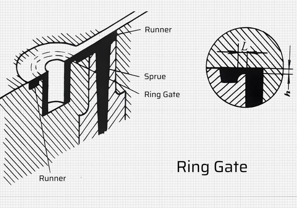
Ring Gate
The ring gate is a variation of the rectangular gate and is set around the cavity, resembling a disc-shaped gate. It shares similarities with the diaphragm gate but is positioned outside the cavity. The selection of ring gate size can be treated similarly to the selection of diaphragm gate size.
| Advantages | Disadvantages | Application |
| – Even melt distribution along the circumference | – Difficult gate removal | – Small, multi-cavity molds<br>- Cylindrical plastic parts with long molding cycles and thin walls |
| – Smooth exhaust | – More noticeable gate traces on the side | |
| – Ripple-free and fusion-free flow | – Gate residue removal required for aesthetic purposes | |
| – Reduced internal stress and deformation |
Film Gate
The film gate is a variation of the side gate. It utilizes a parallel runner, known as a parallel runner, which is aligned parallel to the side of the cavity. The length of the parallel runner can equal or exceed the width of the molded part. The melt is evenly distributed within the parallel runner and enters the cavity at a controlled and uniform speed. Its thin, flat slit shape characterizes the film gate, typically 0.25mm to 0.65mm thick. The width of the gate slit is usually 0.25 to 1 times the width of the cavity at the gate, while the length of the slit is approximately 0.6 to 0.8mm.
| Advantages | Disadvantages | Application |
| – Uniform and smooth melt flow – Reduced internal stress – Effective gas removal | – Difficult gate removal – Presence of shear marks | – Thin plate plastic parts – Large molding area – Controlling deformation of PE and similar plastics |

Pin Point Gate/Pin Gate
Pin Point Gate (Pin Gate) is a widely used type of gate with a round cross-sectional shape and a small size. The size of the pin gate is crucial to ensure proper mold opening and prevent stress on the molded part. The diameter of the gate is typically between 0.6 to 2.8mm, and the length ranges from 0.7 to 1.5mm.
| Advantages | Disadvantages | Application |
| Location flexibility | High-pressure loss, requiring higher injection pressure | Injection molding of low-viscosity plastics and plastics sensitive to shear rate |
| Improved flow rate and friction | Complex mold structure, often requiring a three-plate type mold (two-plate type mold can be used in hot runner molds) | Suitable for multi-cavity center feed molds |
| Automatic gate removal | The high flow rate at the gate can cause increased molecular orientation and potential cracking. | |
| Reduced residual stress at the gate | Prone to warpage deformation in large or easily deformable plastic parts | |
| Faster solidification at the gate |

Submarine Gate
Submarine Gate, also known as a Tunnel Gate, is an advancement of the Pin Gate design that addresses the complexities of Pin Gate molds while retaining their benefits. It provides flexibility in the placement, allowing for positioning on either the moving or fixed mold side. The Submarine Gate can be discreetly placed on the inner surface or sides of the molded part and on the bars, columns, or parting surface. Alternatively, one can conveniently set it using the mold’s ejector rod. Typically, the Submarine Gate assumes a conical shape and angles between 20° and 40° relative to the cavity.
You can choose the gate size based on the dimensions of the Pin Gate.
| Advantages | Disadvantages | Application |
| – Hidden gate placement preserves product appearance. | – Difficult to process due to the submerged and oblique direction of the gate. | – Suitable for plastic parts with one-sided feeding. |
| – Automatic gate removal enables production automation. | – Not suitable for thin-walled products due to high-pressure loss and easy condensation. | – Commonly used in two-plate molds. |
| – No spray marks or airlines on the product surface. | – Cutting off the gate can be challenging for strong plastics like PA. | |
| – Brittle plastics like PS may break and block the gate. |

Tab Gate
The Tab Gate, which is an evolution of the side gate, serves as a typical impact gate. The gate is often square or rectangular, although a rectangular or semi-circular shape is preferred, while the runner is preferably circular.
| Advantages | Disadvantages |
| 1. Smooth and even melt flow into the cavity | 1. Difficult gate removal and leaves a significant trace |
| 2. Improved fluidity of the melt due to increased temperature | 2. Longer and more complicated flow channel |
| 3. Residual stress at the gate does not affect molded part quality | |
| 4. Reduced internal stress in the plastic |
Matching of Gate Type and Resin
| Type | PVC | PE | PP | PC | PS | PA | POM | AS | ABS | PMMA | SFT |
| Direct gate | √ | √ | √ | √ | √ | √ | √ | √ | √ | √ | √ |
| Pin gate | √ | √ | √ | √ | √ | √ | √ | √ | |||
| Submarine Gate | √ | √ | √ | √ | |||||||
| Side Gate | √ | √ | √ | √ | √ | √ | √ | √ | √ | √ | |
| Overlap Gate | √ | √ | √ | √ | |||||||
| Fan Gate | √ | √ | √ | ||||||||
| Film Gate | √ | √ | √ | ||||||||
| Diaphragm Gate | √ | √ | √ | √ | √ | ||||||
| Ring Gate | √ | √ |
Tips for choosing the location of injection mold gates
Requirements for Mold Gate Location
When selecting the gate location, one should aim to minimize visible gate marks and weld lines on the final product.
The gate location should consider the product’s functional requirements, such as ensuring proper filling, packing, and part performance.
The gate location should take into account the ease of mold design and manufacturing, including considerations for mold complexity and feasibility.
When choosing the gate location, one should select it to minimize any potential deflection or distortion of the product during the molding process.
The gate location should facilitate easy removal of the gates after completing the molding process.
The gate location should enable easy control of the molding process parameters, such as melt flow, pressure, and cooling, to ensure consistent and high-quality part production.
Injection Mold Gate position selection
Position the gate to ensure simultaneous filling of all corners of the cavity.
The plastic flow rate should remain uniform and stable throughout all stages of the injection process.
The gate should be placed in the thick part of the product’s wall thickness, allowing the molten plastic to flow from the thick section to the thin section, facilitating complete mold filling.
The gate location should minimize the length of the plastic filling process to reduce pressure loss.
The gate should be located in a part of the cavity that facilitates gas removal.
The gate should not direct the melt directly into the cavity to avoid swirling flow and spin marks, particularly with narrow gates.
Consider potential issues such as weld marks, bubbles, depressions, insufficient injection, and material spraying.
Choose the gate location to avoid visible weld lines on the product’s surface. If you can’t avoid weld lines, select the gate location to minimize their impact.
For circular or cylindrical parts, cold material wells should be added at the melt pouring point to prevent the creation of weld lines.
Gate design should prevent melt fracture.
Avoid placing the gate on one side when the product has a large projected area to ensure even injection force distribution.
Position the gate in a way that does not affect the product’s appearance.
Do not place the gate in areas of the product subjected to bending or impact loads, as these areas tend to have lower strength.
In injection molds with long and thin cores, the gate should be located far from the core to prevent deformation caused by material flow.
You can use compound gates for large or flat plastic parts to prevent deflection, deformation, and material shortage.
The gate design should facilitate easy water outlet operation, preferably through automatic means.
Defects and solutions in injection molding gate
Defects in injection molding gates can occur due to various factors, including gate design, material properties, process conditions, and mold configuration.
| Defect | Cause | Solution |
| Gate vestige or gate mark | Large gate size or improper gate shape | – Use a smaller gate size or change the gate shape |
| Improper gate location | – Optimize gate location to reduce the visibility of the mark | |
| Insufficient gate filling | – Adjust injection pressure, speed, or temperature | |
| Gate blush or discoloration | Thermal degradation or insufficient melt temperature | – Increase melt temperature |
| Inadequate heat transfer | – Adjust mold temperature | |
| Material selection and additives | – Use materials with improved heat stability or additives | |
| Gate shear or flow lines | Inadequate gate design | – Optimize gate design to promote a smoother flow |
| Insufficient injection speed | – Increase injection speed | |
| Improper mold temperature | – Adjust mold temperature | |
| Gate freezing or blockage | Small gate size or improper gate design | – Increase gate size or modify the design |
| Improper process parameters | – Optimize injection pressure and temperature | |
| Material selection and additives | – Use materials with better flow properties or additives | |
| Gate burrs | Improper gate size or shape | – Use appropriate gate size and shape |
| Inadequate cooling and ejection systems | – Optimize cooling and ejection systems | |
| Mold maintenance and cleaning practices | – Implement proper mold maintenance and cleaning practices |
Wrapping Up
Once you understand the types of gates, what often tests mold designers in injection molding factories is gate placement. Because each client’s product structure and material vary, there’s no fixed correct answer for gate placement. Selecting gate placement requires a certain level of practical experience for mold designers.
Usually, clients in injection molding factories have specific requirements for gate marks on products, directly influencing the appearance of products or parts. If you’re a peer of FirstMold or aspire to excel in this industry, mastering the selection of gate placement is essential. If you have any questions, feel free to contact [email protected], and we’ll gladly answer them for you.