In our previous discussions, we explored the concept of mold sprues as an integral part of the feeding system. Today, let’s delve into the next structure of this system – the mold runner and sub-runner. Like the sprue, many mold designers often overlook the structure of runners and sub-runners due to their fixed and relatively simple design standards. If you want to become a top-notch mold designer and deliver top-quality molds that satisfy clients, please master every detail.
What Is Runner And Sub-Runner?
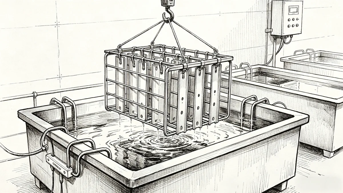
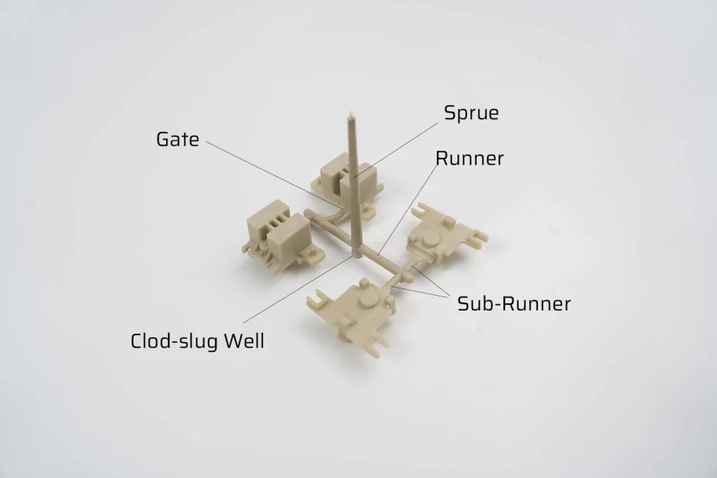
As usual, let’s first review the entire feeding system for a better understanding of this article. The feeding system comprises structures that transfer molten plastic from the barrel of the injection molding machine into the mold cavity. After ejecting molten plastic from the machine’s nozzle, the molten plastic passes through the sprue, runner, sub-runner, and gate, and finally fills the cavity to form plastic parts.
Hence, the runner is the passage between the sprue and the gate, serving as the transitional section where the molten plastic flows from the sprue into the cavity, responsible for smoothly redirecting the flow of the melt. In multi-cavity molds, it plays a role in distributing the melt to each cavity. It’s worth noting that in single-cavity molds, runners are generally not included, which is related to the layout of the cavity.
Design Guidelines for Mold Runners
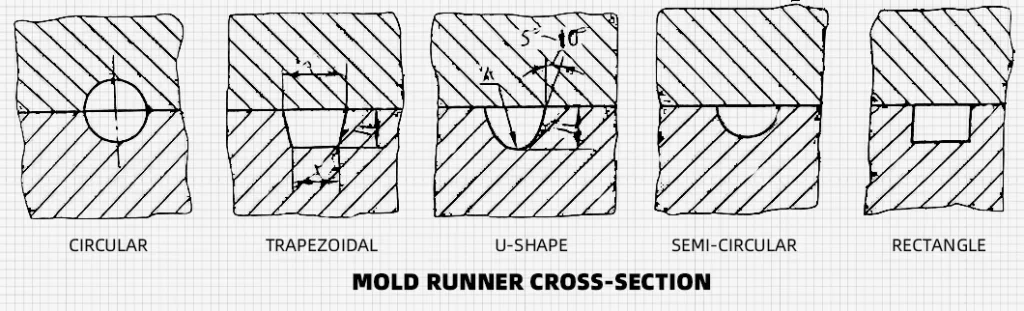
The shape of the mold runner cross-section
Rectangular cross-section:
Rectangular-shaped runners are common. They offer advantages such as ease of manufacturing, simple tooling design, and uniform flow distribution. The dimensions of the rectangular cross-section can be adjusted based on the specific molding requirements of the part.
Trapezoidal cross-section:
Trapezoidal-shaped runners are another option in mold runner design. This shape helps promote better flow and reduces pressure drop, resulting in improved filling of the mold cavities. The wider end of the trapezoid is typically connected to the sprue, while the narrower end is connected to the gate.
Circular cross-section:
In some cases, circular-shaped runners may be the first choice. These runners offer excellent flow characteristics and are particularly suitable for parts with complex geometries or when a balanced flow is required. The diameter of the circular cross-section should be carefully determined to ensure optimal flow and minimize pressure loss.
Semi-circular cross-section:
A semi-circular-shaped runner features a half-circle profile. This shape promotes smooth material flow and helps minimize pressure drop. It is often used when balanced flow and reduced pressure loss are critical. The diameter of the semi-circular cross-section should be appropriately sized to accommodate the flow requirements of the specific injection molding process.
U-shaped cross-section:
A U-shaped runner has a curved bottom and two vertical walls that form the shape of a “U.” This design facilitates efficient material flow and allows for easier separation of the runner system from the molded part. The U-shaped cross-section is commonly employed when easy removal of the runner system is desired or when gating is located at the bottom of the part.
The selection of the cross-sectional shape depends on factors such as material properties, part design, mold layout, and production requirements. Each shape has its advantages and is chosen based on the specific needs of the molding process.
The Size Of The Mold Runners And Sub-Runners
The shape and size of the mold runners depend on various factors, including the product design, mold construction, and the specific requirements of the injection molding process. While the product size and wall thickness may influence the runner design, it is not accurate to say that larger cross-sectional runners are always more effective in facilitating the filling process. Material flow behavior, part geometry, gate location, and process parameters determine the optimal runner design.
Additionally, the length of the runner does not directly affect the viscosity of the plastic. The material properties and processing conditions primarily determine viscosity.
| Materials | Runners Diameter(mm) |
| ABS / SAN(AS) | 4.8~9.5 |
| POM | 3.0~10 |
| ACRYLIC | 1.6~10 |
| CA | 1.6~11 |
| PA66 | 1.6~10 |
| PPO | 6.4~10 |
| PPS | 6.4~13 |
| PC | 4.8~10 |
| PE | 4.8~9.5 |
| PP | 1.6~10 |
A well-designed runner can significantly impact the overall performance and efficiency of the injection molding process:
Mold Runners & Sub-Runners Arrangement
There are two types of mold runner arrangements: balanced and unbalanced. In a balanced runner system, the runners’ length, shape, and cross-sectional dimensions from the sprue to each cavity are designed to be equal. This helps achieve thermal balance and plastic flow balance in each cavity, resulting in consistent part quality. On the other hand, an unbalanced runner system allows the plastic to enter each cavity at different times, leading to variations in the filling process and potentially producing different parts. However, unbalanced runner systems can offer advantages such as more compact cavity arrangements, reduced template size, and shorter overall runner length.
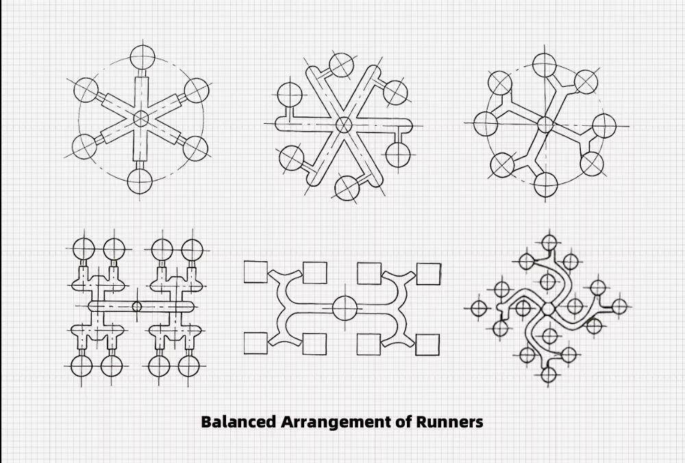
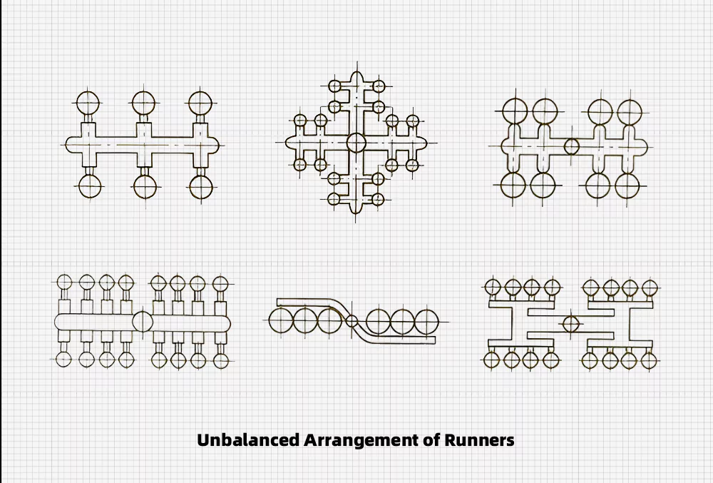
Whether the runner system is balanced or unbalanced, it is important to ensure that the cavities are symmetrical with the center of the mold base. This ensures that the projected center of the cavities and runners align with the center of the clamping force of the injection machine. By doing so, we can avoid additional tilting moments during an injection.
A balanced runner system is advantageous as it allows for consistent injection and holding pressure across all cavities. This is particularly beneficial for multi-cavity molds where maintaining uniformity in producing all products is desired.
Design Principles of Runners & Sub-Runners
- Ensure the molten plastic enters the cavity swiftly with the shortest distance and minimal heat pressure loss.
- Enable the melt to feed into the cavity simultaneously from various gates under identical temperature and pressure conditions.
- Although larger cross-sectional areas facilitate molding and ensure adequate packing pressure, considering material saving, aim for smaller cross-sectional areas to minimize plastic consumption, which also reduces cooling time.
- To conserve material and aid cooling, strive for a minimal surface area to volume ratio in runners.
- The surface roughness of runners shouldn’t be too low to prevent dragging cold material into the cavity; typically, an Ra value of 1.6 μm is sufficient.
- Runners and gates are usually connected with slopes and arcs, promoting the flow and filling of molten plastic while reducing flow resistance.
Is It Necessary To Design The Sub-Runner In The Mold Runner Design
A sub-runner is typically used when there is a need to divide the flow of molten plastic into different directions within the mold cavity. It can help facilitate the filling of complex or multi-cavity molds by directing the flow to specific areas or components of the part.
However, in some cases, a simple runner design without a sub-runner may be sufficient to achieve the desired mold filling and part quality. Whether to incorporate a sub-runner or not depends on the specific requirements of the part design and the injection molding process.