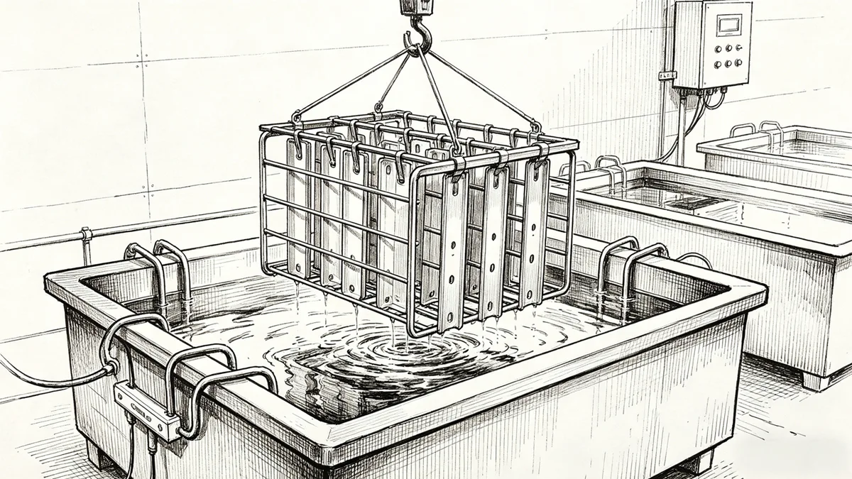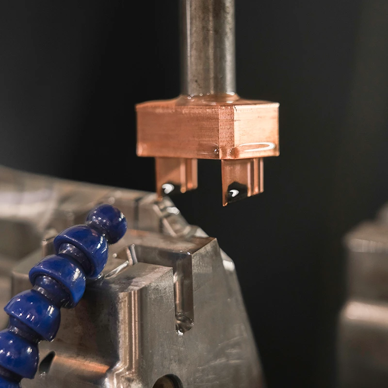
Electrodes are commonly used in mold processing. They serve as the tool for spark machining in Electrical Discharge Machining (EDM), mainly used for processing the cavities in molds.
What is an Electrode?
Electrodes are tools used for spark machining. In mold processing, some parts are either too complex or have small internal angles and fillets that conventional tools cannot reach. Alternatively, if the workpiece cannot be machined due to excessive tool length, electrodes are used for EDM.
Materials for Electrodes
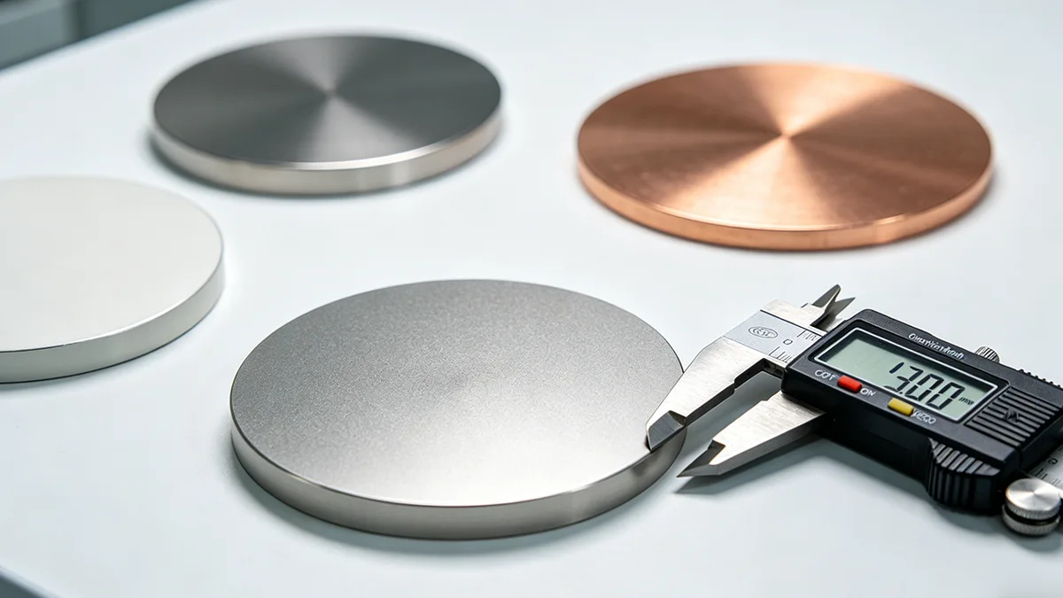
1. Red Copper
Red copper is widely available and has good electrical conductivity. It can be stably processed under challenging conditions without easily generating an electric arc and with minimal processing loss. It can achieve high precision with a surface roughness better than Ra1.25μm using fine machining. The process can maintain sharp edges and delicate shapes.
However, its mechanical machining performance is inferior to graphite, and it is difficult to grind. It has low mechanical strength, which is not conducive to clamping, adjusting, and maintaining stable processing over time. Its high density increases the burden on the processing feed system and raises system requirements, making it unfavorable for electrode installation and adjustment.

2. Graphite
Compared to red copper electrodes, graphite has several advantages:
1). less electrode wear (1/5 to 1/3 of that of red copper during rough machining).
2). Faster machining speeds (about 1.5 to 3 times that of red copper).
3). Better machinability with cutting resistance being a quarter of that of red copper.
4). Double the processing efficiency, lighter weight (1/5 that of red copper), suitable for large electrodes.
5). High-temperature resistance, and low thermal expansion coefficient (about 1/4 of red copper).
Its disadvantages include brittleness (which can be reduced by soaking in working fluid), susceptibility to damage, prone to arc burn, and greater loss in precision machining with a surface roughness only achieving up to Ra2.5μm. Not easily formed into thin plates or sharp edges.
3. Copper Tungsten and Silver Tungsten Alloys
Copper tungsten electrodes, due to their high thermal conductivity, low loss rate, low thermal expansion. Besides, the high melting point of tungsten is widely used in mold steel and tungsten carbide workpieces as well as in precision machining. Copper tungsten and silver tungsten alloys have comparable machinability, good processing stability, and low electrode loss, but they are expensive, costing approximately 40 and 100 times that of copper, respectively.
4. Brass
Brass electrodes have higher wear and slower processing speeds than red copper but experience fewer short circuits during discharge, providing stable processing. Currently, brass electrodes are generally not used in EDM shaping but are still used in low-speed wire cutting.
5. Steel
Steel is used as an electrode material due to its good machinability, but it has poorer processing stability. In steel die processing, the machining speed is 1/3 to 1/2 that of red copper, and the electrode wear rate is 15% to 20%, which cannot achieve low loss.
Summarizing the application characteristics of these common electrode materials, the electrode materials for EDM should meet the following basic performance requirements:
- High melting point, the higher the melting point of the electrode material, the smaller the relative electrode loss.
- Good thermal conductivity, which allows the heat generated by discharge to dissipate quickly, rapidly restoring the insulating properties of the machining medium and suppressing the occurrence of arc burn.
- Good electrical conductivity, which facilitates ionization and meets the basic conditions for discharge.
- Low thermal expansion coefficient, which allows the electrode size to remain stable during EDM, ensuring machining precision.
- Good mechanical properties, easy to machine and with good deformation resistance.
Disassembling Electrodes
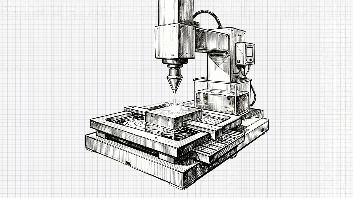
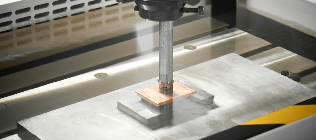
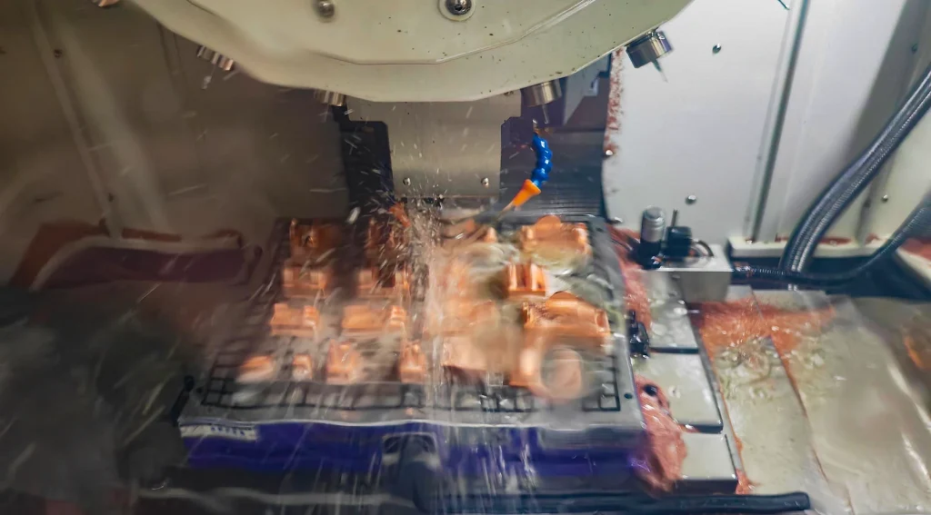
The processing methods for electrodes typically involve CNC milling or wire cutting. When electrodes have complex concave and convex surfaces, CNC milling is necessary. Sometimes, an electrode cannot be machined as a whole and needs to be divided into two or more parts for machining. This process of dividing electrodes into various parts to accomplish discharge machining for different parts of the mold is called disassembling electrodes.
Purpose of Disassembling Electrodes
In plastic mold manufacturing, EDM (Electrical Discharge Machining) is almost indispensable. The machining speed of EDM directly affects the cycle, quality, and cost of mold manufacturing. Therefore, a detailed analysis and rational disassembly of the electrodes (copper electrodes) are essential. The quality of disassembly directly determines the level of mold manufacturing, machining speed, manufacturing costs, and even the overall structure of the mold. The capability to disassemble electrodes reflects the comprehensive level of mold designers, the correctness of structural thinking, and the level of machining technology. Rational disassembly of electrodes can have the following effects:
- Simplify the machining of molds.
- Improve the mold structure.
- Shorten the manufacturing cycle of molds.
- Enhance the quality of molds.
- Improve the dimensional accuracy of mold cores and cavities.
- Save on the cost of electrode materials.
Electrode Disassembly Process
The disassembly of electrodes is an essential part of mold processing. The quality of electrode disassembly directly impacts the machining speed and quality of the mold. Designers must communicate extensively with mold makers and EDM technicians to gather and summarize experiences. Based on the processing conditions of our company, discuss and decide on a reasonable disassembly plan.
1. Determine the Disassembly Location of the Electrodes
Parts that cannot be machined by CNC machines typically need electrode disassembly, such as right angles, sharp angles, narrow grooves (if the company has high-speed machines and smaller tools, direct machining of narrow grooves is possible), and text areas. Electrode disassembly must analyze the workpiece, determine the location of disassembly, and carry it out in the most material-efficient, fastest, and most effective way.

2. Disassembly of the Forming Parts of the Electrodes
The disassembly of the forming parts of the electrodes generally involves extracting surfaces or calculating differences to approximate the shape, followed by subsequent editing to obtain the structure of the electrode forming parts. When disassembling forming parts, it is important to extend as much as possible, but interference should be avoided, and it should ensure that the disassembled electrodes can effectively form the required parts.

3. Drawing the Flushing Position
The flushing height for EDM is typically set 2 to 5 mm above the highest part of the workpiece, facilitating the removal of residues during EDM machining. EDM generates a lot of residues, and if not removed promptly, secondary discharges can damage the electrodes, and excessive carbon buildup can damage the workpiece, especially in deep cavities, leading to defects during injection molding. The flushing position is generally completed using offset surfaces and stretching functions.

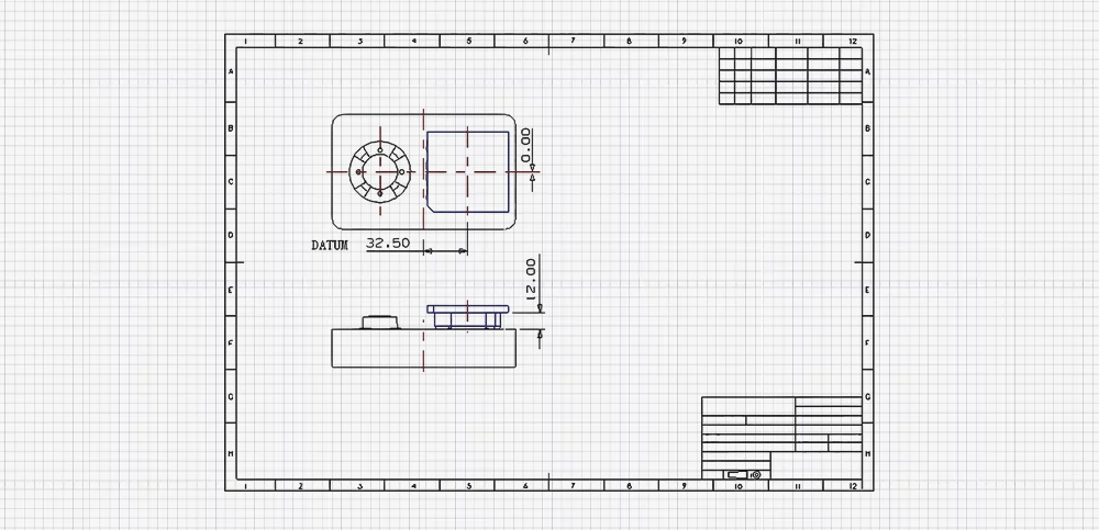
4. Drawing the Datum
The DATUM of the electrode is very important as it can be used for centering, calibration, and touching numbers, directly determining the accuracy and correctness of the forming parts. The external dimensions of the datum are generally integers, with a typical distance of 3 to 8 mm from the edge of the datum to the edge of the forming part, and a height of 5 to 15 mm.

The method for drawing the datum typically involves two approaches:
one is to uniformly enlarge along the edges of the forming parts, resulting in decimals from the center of the datum to the center of the workpiece.
The other is to preset the center of the datum and the center of the workpiece as integers, not considering the uniform enlargement of the forming part edges, which has the advantage of avoiding dimensional errors during EDM machining, reducing the chance of errors. The second method is generally recommended.
The orientation of the electrode is very important, and different factories have different representation methods. Generally, three corners of the electrode are either chamfered or not, corresponding to the chamfered datum angles of the workpiece, and then codes are marked on the electrode to differentiate between rough and fine electrodes.

5. Electrode EDM Diagram
The electrode EDM diagram is mainly used to guide the EDM technician during operation. The drawing should be as simple as possible, without too many views and dimensions, requiring only the expression of the electrode positioning dimensions, EDM gap, and datum position. If these three elements are conveyed, the drawing is viable.
Principles of Electrode Disassembly
Disassembling electrodes is a complex task that generally follows these eight principles:
- Fully consider the product’s appearance requirements to meet its technical specifications.
- Distinguish the discharge differences between large and small glue position electrodes.
- Thoroughly consider and assess the difficulty of processing electrodes to ensure efficient and feasible machining within the company.
- Fully consider and differentiate the precision requirements of each electrode and each part, avoiding the blind pursuit of high standards and coordinating the use of various types of machining equipment effectively.
- Aim to reduce the manufacturing costs of molds. Cost is the most crucial indicator in mold processing. Only reasonable disassembly of electrodes can maximize economic benefits.
- Fully consider the arrangement and impact of machining processes. Only with a rational process arrangement can the entire set of molds be produced well, quickly, and economically.
- Balance the various machining processes and the overall processing speed. For the entire set of molds, consider electrodes for fixed molds, movable molds, sliders, inclined push rods, and inserts, and balance these globally during disassembly.
- Where conditions permit, minimize human errors during the machining process.
Considerations for Electrode Disassembly
When disassembling electrodes, consider the feasibility, practicality, non-deformability, convenience of processing, cost, and aesthetic appearance of the electrodes. The fewer electrodes disassembled, the better.
1. Design and Fabrication of Whole Electrodes
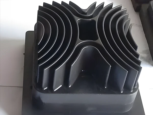
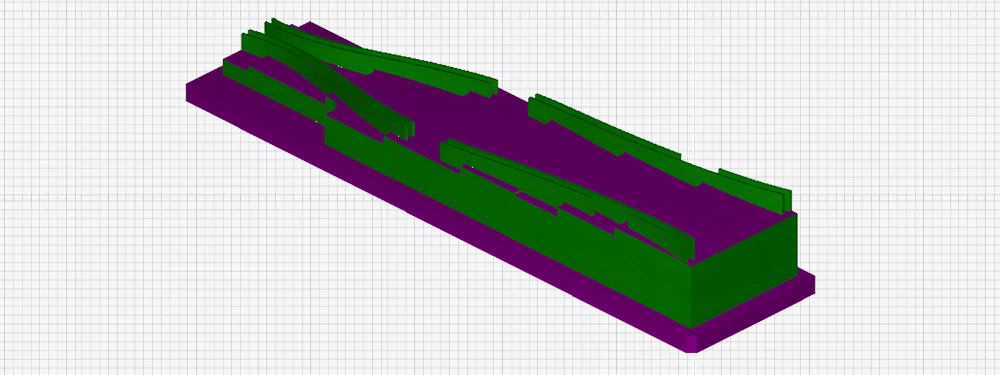
Whenever possible, disassemble whole electrodes. However, consider the feasibility of processing and try to complete it in one step. If it can’t be done in one step, disassemble into multiple electrodes. Some whole electrodes are special and require multiple processing steps, such as those shown in the picture below using CNC milling, wire cutting, and electrode corrosion processes. These electrodes generally need to meet product precision, and disassembling them into multiple electrodes can result in joint marks, making it difficult to ensure product precision.
2. Disassembling Individual Electrodes
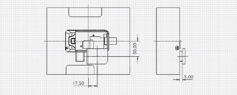
After disassembly, the electrodes must be machinable. Sometimes whole electrodes are difficult to process, have unreachable dead corners, or require tools that are too long or too small, making it reasonable to consider disassembling an additional electrode. Sometimes, local clean-up electrodes are needed, and their processing is not difficult, but it is essential to understand the electrical discharge machining offsets and calibration standards clearly. During CNC machining, it’s challenging to directly machine the circled areas in the mold core, and it’s also difficult to design and process a single electrode for EDM. Disassembling the electrode into parts (b) and (c) in the picture makes machining much easier.

3. Disassembling Rib Electrodes
To increase the strength of the thin plate-like structures designed for plastic products initially, these are called ribs. Ribs are both narrow and deep, making them difficult to machine directly. Generally, rib electrodes need to be designed. These electrodes are prone to deformation during machining. Use new tools with smaller diameters and moderate feed rates. First, machine the length dimensions accurately, but leave some margin (like 1mm) for the width dimensions, then machine the width, moving the tool on both sides simultaneously, without encircling the entire outline. Also, each cut should have a depth of 0.2 to 1mm. Too deep a cut is not advisable.
4. Material Situation
Before disassembling electrodes, first understand the company’s material situation and strive to make the most of the materials. Imported copper generally requires adding 1 to 1.5mm per side to the standard dimensions, which is sufficient for most purposes. Domestically forged copper is less standardized, and adding 2mm per side is recommended.
5. Flushing and Calibration Setup
Set the straight part of the electrode to 2 to 5mm to facilitate flushing by the EDM machine. Set the XY-axis calibration to about 3 to 8mm per side, with a base height of more than 5mm.
6. Electrode Datum Design
It’s recommended to use three rounded corners and one angled corner for the electrode base, aligning the angled corner with the mold cavity’s datum. Align the center of the electrode with the mold cavity’s datum using integers.
7. Efficient Electrode Disassembly
Try not to disassemble the electrode separately. If it’s possible to disassemble the whole, do it together to save material and discharge time. When machining is difficult, use wire cutting or an engraving machine to clean the corners.
8. Material Conservation in Disassembly
Electrodes with significant height differences should be disassembled into multiple electrodes to save on material.
9. Processing Symmetric Electrodes
Symmetric electrodes are often processed together, moving the number during machining. Similar-shaped electrodes should be distinguished (e.g., adding an extra angled or rounded corner), and extend the joint between two electrodes by 1mm.
10. Post-Disassembly Inspection
After disassembly, fit the electrodes into the workpiece to carefully check for interference. Check if similar and symmetric electrodes are reasonably disassembled, and verify that the distances and rotation centers of translated or rotated electrodes are correct.
11. Precision in Electrode Finish
The roughness and fineness of the electrodes are often determined by the product’s appearance requirements. Sometimes, to save copper, after completing the electrode, lower the overall curved surface design of the electrode, perform precision milling on the electrode, and then carry out precision EDM.
12. Machining Deep Cavities
For narrow and deep cavities in molds, where tools cannot reach for rough machining, it’s often necessary to do rough and fine electrodes either partially or wholly.
13. Strengthening Rib Electrodes
When designing rib electrodes, to enhance the strength of the electrode and prevent deformation, change the angle of the rib and design a reinforced base.
13. Ensuring Mold Sharpness
Separate the glue face of the mold cavity and core from the pillow face when disassembling the electrode to ensure the sharpness of the mold cavity.
14. Maintaining Electrode Coordinate Integrity
When designing disassembled electrodes, it’s recommended not to easily change the electrode’s coordinate system. Use assembly disassembly for one electrode per drawing file. Layers can also be used to distinguish between electrodes.