


Termin “dopasowanie” ma kluczowe znaczenie w przypadku części ruchomych. Potężna maszyna z licznymi ogniwami i zespołami może ulec awarii wyłącznie z powodu zbyt wąskiego luzu, co powoduje, że części ślizgają się po sobie, zamiast przenosić siły w całym układzie. Wyobraź sobie, że projektujesz wał silnika, który ma zostać połączony z otworem w celu przenoszenia mocy. Okazuje się, że wał nie przechodzi przez otwór. Musisz oddać go z powrotem do obrabiacza, co wiąże się z dodatkowymi kosztami. Może się również zdarzyć, że łożysko obraca się luźno na wale, podczas gdy powinno być ściśle osadzone. Wyobraź sobie również kołek, który pęka w obudowie, w której miał się osadzić. Scenariusze te ilustrują awarie konstrukcyjne wynikające z przeoczeń dotyczących dopasowań. Dopasowania między współdziałającymi częściami oraz tolerancje nie zostały dobrze zdefiniowane podczas procesu projektowania.
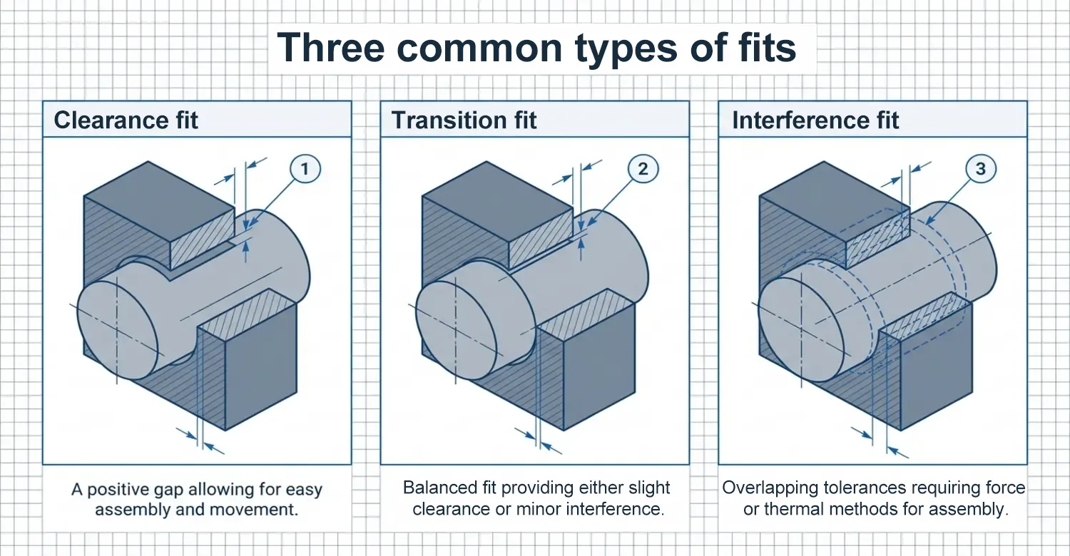
“W inżynierii mechanicznej termin ”pasowanie” oznacza relację wymiarową między dwiema współpracującymi częściami. W większości przypadków dotyczy to wału i otworu. Pasowanie określa sposób, w jaki te współpracujące części oddziałują na siebie. W projektowaniu inżynierskim wyróżnia się trzy powszechne rodzaje pasowań: luzowe, przejściowe i ciasne. W przypadku pasowania luzowego zawsze występuje dodatni luz, który umożliwia montaż i przemieszczanie elementów. W przypadku pasowania z wciskiem występuje tolerancja nakładania się. W takim połączeniu konieczne jest zastosowanie dodatkowej siły lub metod termicznych. Pasowanie przejściowe plasuje się pomiędzy tymi dwoma skrajnościami. Powoduje ono powstanie niewielkiego lub nieznacznego luzu, w zależności od dostępnej tolerancji.
W niniejszym przewodniku szczegółowo omówiono te trzy rodzaje pasowań, ich działanie, zastosowania oraz kwestie związane z tolerancjami. W niniejszym opracowaniu będziemy używać terminów „otwór” i „wał”, nawet jeśli materiał nie ma kształtu okrągłego. Otwór to element wewnętrzny, natomiast wał to element zewnętrzny.
Czym jest pasowanie z luzem?
Pasowanie luzowe jest najczęściej spotykanym rodzajem pasowania, w którym otwór jest nieco większy od trzpienia, co powoduje powstanie zamierzonej szczeliny między obiema częściami. Szczelina między dwiema powierzchniami, zwana po prostu luzem, jest celowo zaprojektowana tak, aby umożliwić swobodny ruch bez tarcia i zakleszania. Tolerancje obu elementów decydują o wielkości luzu, zapewniając płynne dopasowanie bez nadmiernego luzu.
W konstrukcji tego typu dopasowanie pozwala inżynierom uniknąć montażu na siłę lub wciskania. Wałek jest mniejszy od otworu, co zapewnia skuteczne dopasowanie obu powierzchni.
Pomiar pasowania luzowego
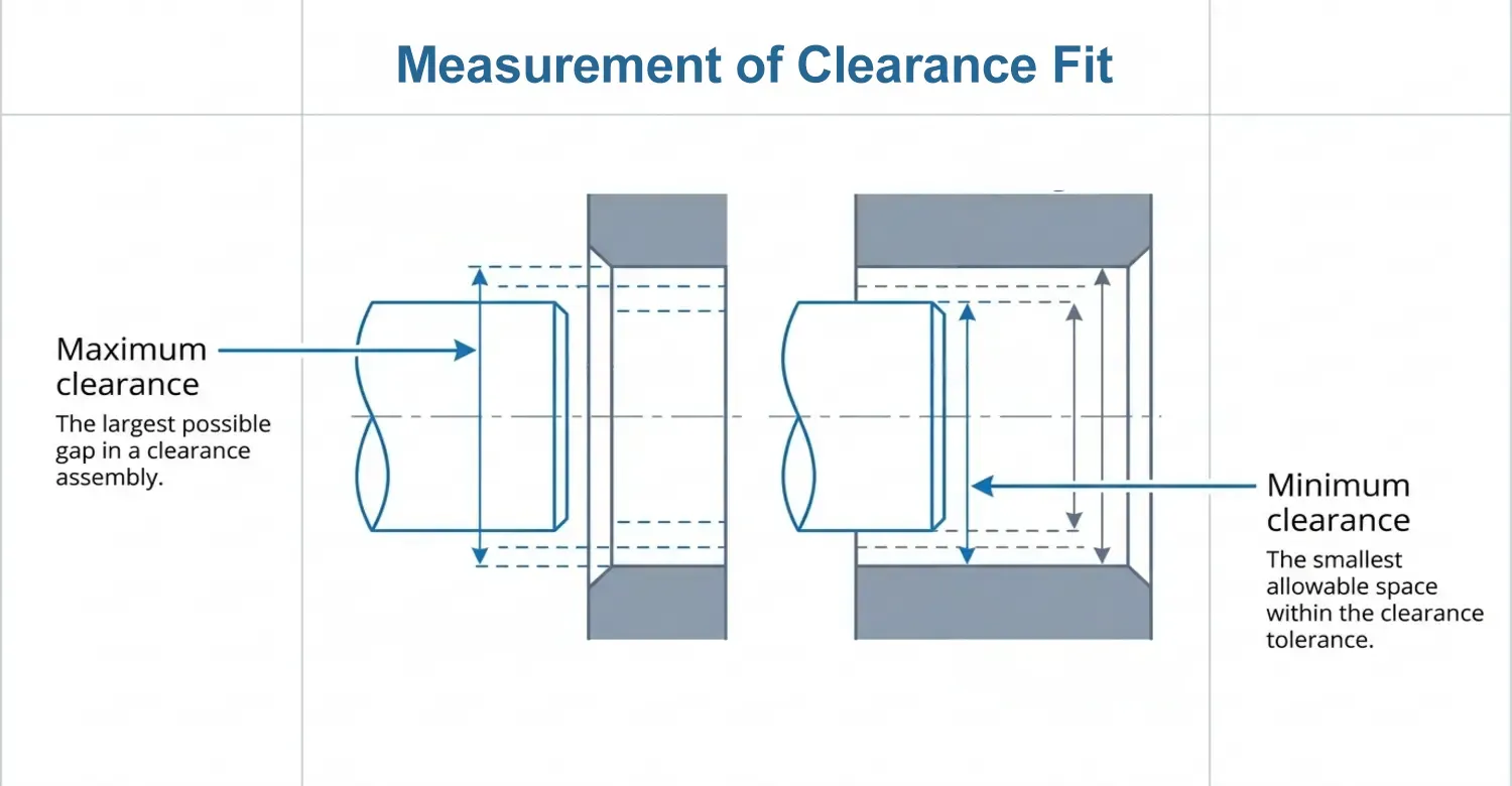
Luz pasowy mierzy się za pomocą mikrometrów lub suwmiarek. Za pomocą tych narzędzi można określić maksymalny i minimalny luz. Luz maksymalny to odległość między największym otworem a najmniejszym wałem. Z kolei luz minimalny odnosi się do odległości między najmniejszym otworem a największym wałem. Luz mierzy się w milimetrach i oblicza się go według wzoru:;
Prześwit = średnica otworu – średnica wału
Jeśli otwór ma średnicę 6,36 mm, a wał – 6,12 mm, to luz wyniesie 0,24 mm.
Poziomy tolerancji dla pasowania luzowego
Podczas projektowania z uwzględnieniem luzu należy określić tolerancje dla procesu produkcyjnego, aby zminimalizować błędy. Poziomy tolerancji wskazują, jak duże odchylenia powinien mieć luz. Na przykład, jeśli otwór o średnicy 20 mm i wał o średnicy 19 mm mają być wykonane z tolerancją ±0,020 mm, oznacza to, że każdy otwór wyfrezowany w zakresie od 20,00 mm do 20,020 mm będzie zapewniał luz w połączeniu z każdym wałkiem wyfrezowanym w zakresie od 19,00 mm do 19,020 mm. Podobnie można wyfrezować otwór o średnicy w zakresie od 19,98 mm do 20,00 mm oraz wałek o średnicy w zakresie od 18,98 mm do 19,00 mm.
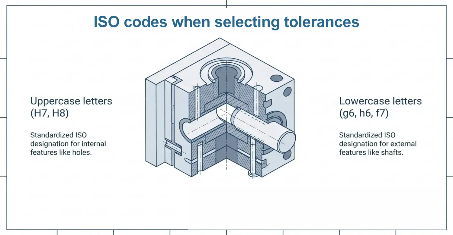
Inżynierowie przy wyborze tolerancji kierują się określonymi normami ISO. Normy te zawierają wielkie litery i cyfry (np. H7, H8) dla otworów oraz małe litery i cyfry (np. g6, h6, f7) dla wałów [1]. Poniższa tabela zawiera zestawienie oznaczeń stosowanych w specyfikacji tolerancji.
| List | Komponent | Znaczenie |
|---|---|---|
| H | Otwór | Mniejsze odchylenie = 0 (otwór zaczyna się od rozmiaru podstawowego) |
| h | Wał | Odchylenie górne = 0 (największy wymiar wału jest równy wymiarowi podstawowemu) |
| g | Wał | Nieco poniżej rozmiaru podstawowego, co zapewnia niewielki luz |
| f | Wał | Znajduje się nieco poniżej podstawowego rozmiaru „g”, co zapewnia większy prześwit |
Liczby oznaczają klasy tolerancji międzynarodowych (IT). Im mniejsza liczba, tym węższa tolerancja i tym większa dokładność obróbki. Tolerancje IT5 i IT6 stosuje się w przypadku wysokiej precyzji. IT7 stosuje się w przypadku ogólnej precyzji inżynierskiej. IT8 i IT9 oznaczają średnią precyzję, natomiast IT10 i wyższe oznaczają tolerancję zgrubną.
Na przykład w kontekście inżynieryjnym, jeśli zaprojektujesz otwór o średnicy 20 mm i wał o średnicy 20 mm z tolerancją H7/h6, oznacza to, że:
- Otwór ma dopuszczalną tolerancję dodatnią, począwszy od wymiaru podstawowego wynoszącego 20,00 mm.
- Wał jest produkowany z dużą precyzją w rozmiarze zbliżonym do rozmiaru podstawowego lub nieco mniejszym, co zapewnia niezawodne połączenie ślizgowe lub pozycjonujące.
W poniższej tabeli przedstawiono niektóre obszary zastosowań dla różnych tolerancji luzu.
| Dopasowanie | Typ | Typowe zastosowanie |
|---|---|---|
| H7/g6 | Ciasne dopasowanie | Wały silników elektrycznych, łożyska precyzyjne |
| H7/h6 | Pasowanie z luzem przesuwnym lub lokalnym | Wały prowadzące, koła pasowe, elementy ustalające |
| H8/f7 | Luźny krój | Maszyny ogólnego przeznaczenia, łatwe w montażu części |
Jakie są rodzaje pasowania z luzem?
Istnieje kilka rodzajów pasowań luzowych, jak opisano poniżej;
- Pasowanie ślizgowe: Wał i otwór są zaprojektowane tak, aby między nimi występował niewielki, kontrolowany luz. Części te ślizgają się po sobie płynnie, bez oporu ani nadmiernego luzu. Przykładami są szyny prowadzące i łożyska liniowe.
- Łatwe dopasowanie przesuwne: Prześwit jest nieco większy niż w przypadku dopasowania przesuwnego. Przesuwanie jest tu jeszcze łatwiejsze. Łatwe dopasowanie przesuwne umożliwia prosty montaż i demontaż dzięki niewielkiej dostępnej szczelinie. Przykładem może być szuflada.
- Dopasowanie „running fit”: To dopasowanie jest luźniejsze niż „slide fit”, ale ciaśniejsze niż „slack running fit”. Przeznaczone jest dla elementów poddanych ciągłemu ruchowi. Przykładem może być taśma przenośnikowa.
- Pasowanie luźne: Charakteryzuje się większym luzem niż pasowanie biegowe. Stosuje się je w elementach, w których dopuszczalny jest niewielki luz lub niewielkie niewspółosiowość. Przykładami są elementy mocujące i regulowane podstawy maszyn.
- Luźne osadzenie: Charakteryzuje się największym luzem. Nadaje się do zastosowań, w których nie jest wymagane dokładne wyrównanie. Przykłady obejmują drzwi przesuwne i panele.
Czym jest pasowanie z wciskiem?
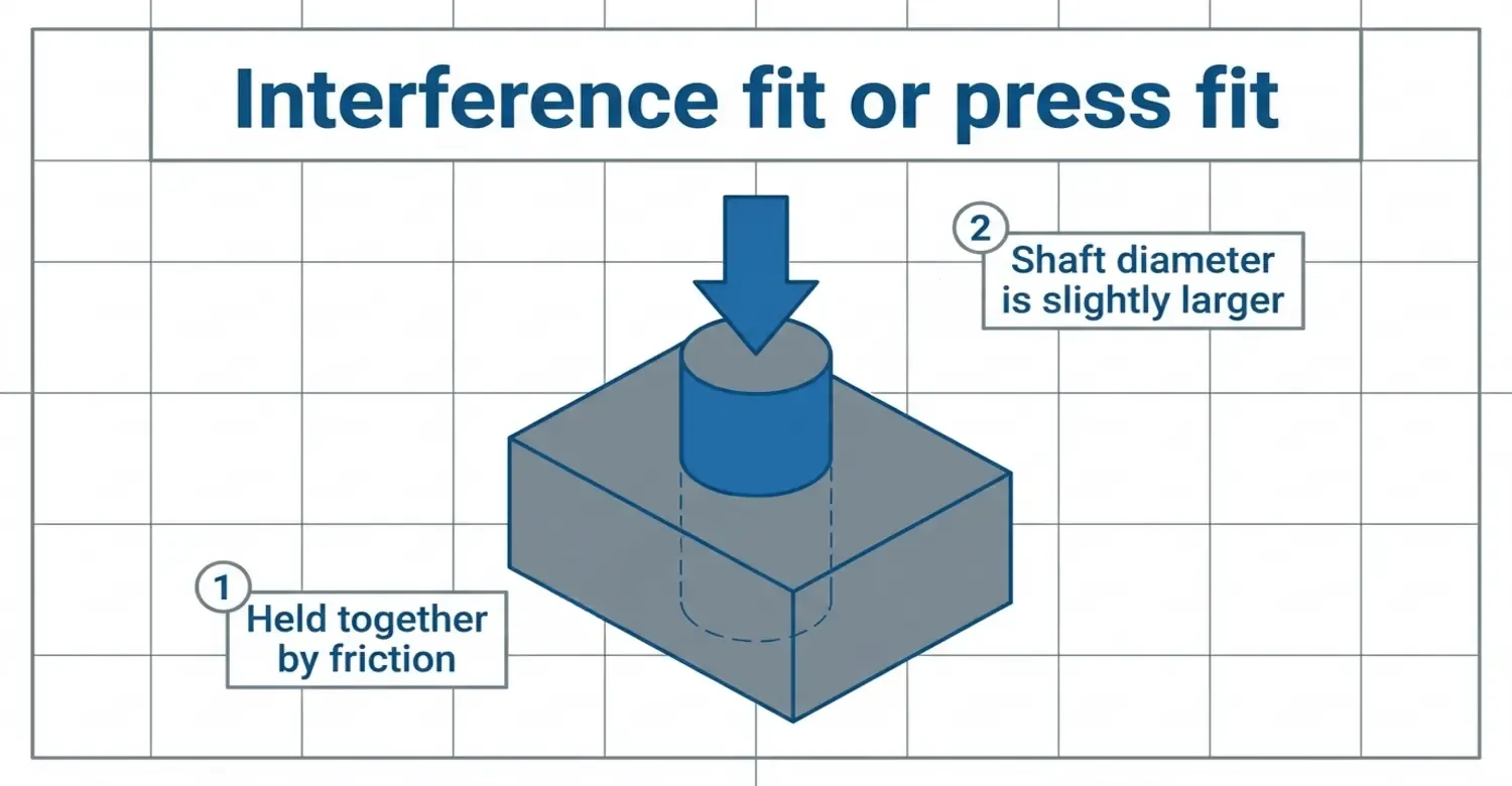
Pasowanie z wciskiem nazywane jest czasem pasowaniem ciernym lub pasowaniem prasowym. Jest to połączenie dwóch ściśle do siebie przylegających elementów, w którym po ich zepchnięciu w stosunku do siebie powstaje połączenie utrzymywane przez tarcie. [2]. W praktyce oznacza to, że średnica wału w tym połączeniu jest nieco większa niż średnica otworu. Połączenie tych dwóch elementów wymaga użycia siły.
Pasowania z wciskiem tworzą mocne, stabilne połączenie, które może mieć charakter trwały lub półtrwały. Tego rodzaju pasowanie stosuje się w kołach zębatych i kołach pasowych, zespołach łożyskowych oraz piastach kół samochodowych, gdzie elementy muszą pozostawać nieruchome pomimo obciążeń i drgań.
Pomiar pasowania z wciskiem przebiega podobnie jak w przypadku pasowania z luzem. Jednak wcisku oblicza się w następujący sposób:;
Różnica = średnica wału – średnica otworu
W połączeniach z wciskiem zazwyczaj stosuje się węższe tolerancje wału, takie jak s6, t6 lub u6, aby zapewnić połączenie wciskane.
Czym jest Transition Fit?
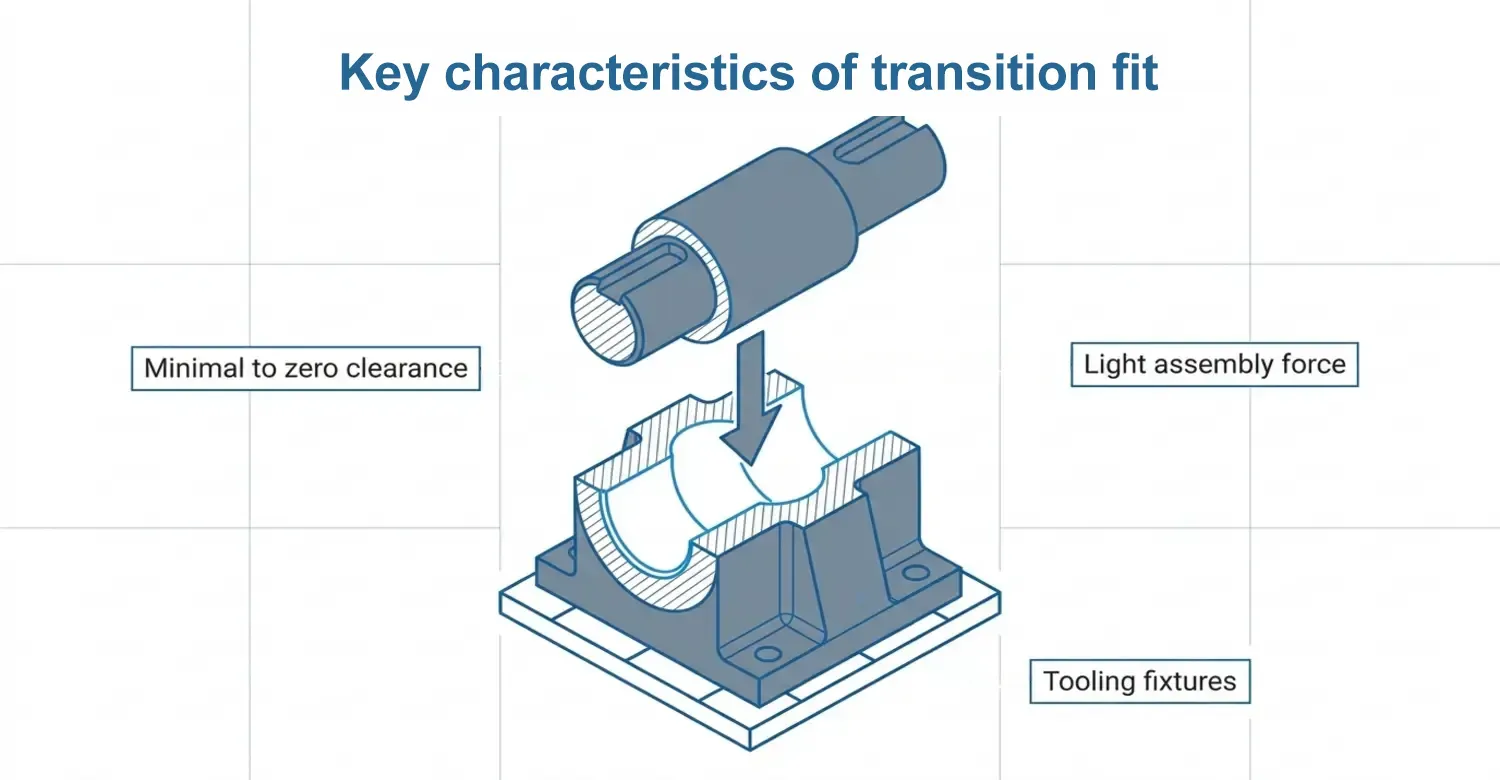
W przypadku tego rodzaju pasowania wał może być nieco mniejszy lub większy od otworu (przed montażem). Pasowanie to stosuje się w celu uzyskania ciasnego, pewnego połączenia między elementami w zastosowaniach wymagających wysokiej precyzji i stabilności. Zapewnia ono wysoką dokładność, a jednocześnie umożliwia demontaż i ponowny montaż połączonych części bez ich uszkodzenia. Pozwala to na demontaż i ponowny montaż łączonych elementów przy jednoczesnym skutecznym przenoszeniu umiarkowanych obciążeń roboczych. Pasowanie to stanowi kompromis między pasowaniem luzowym a pasowaniem z wciskiem. Stosuje się je głównie tam, gdzie kluczowe znaczenie ma precyzyjne wyrównanie. Typowe zastosowania obejmują uchwyty narzędziowe, precyzyjne zespoły, takie jak elementy silników i maszyn, oraz łożyska.
Pasowanie przejściowe jest idealnym rozwiązaniem, gdy potrzebne są elementy, które można montować ręcznie przy użyciu niewielkiej siły, zachowując jednocześnie rozsądną dokładność pozycjonowania. Ten rodzaj pasowania charakteryzuje się niewielkim nadmiarem w zakresie luzu, dzięki czemu doskonale nadaje się do części wymagających sporadycznego demontażu lub tymczasowego ustawienia.
Do kluczowych cech połączenia przejściowego należą: luz minimalny lub zerowy oraz niewielka siła potrzebna do montażu. Połączenie to nadaje się do montażu ręcznego, zapewnia odpowiednią dokładność i umożliwia sporadyczny demontaż.
Zastosowanie pasowania przejściowego w przemyśle
Różne branże wykorzystują elementy przejściowe do różnych celów:
| Przemysł | Przykłady zastosowań | Najważniejsze zalety |
|---|---|---|
| Motoryzacja | Uchwyty łożysk, piasty kół | Łatwa konserwacja |
| Lotnictwo i kosmonautyka | Tuleje prowadzące | Precyzyjne pozycjonowanie |
| Elektronika | Radiatory, uchwyty do mocowania podzespołów | Kompensacja rozszerzalności cieplnej, łatwość konserwacji |
| Medyczny | Obudowy przyrządów | Zgodność ze sterylizacją |
Wnioski
“Pasowanie” to relacja wymiarowa między dwiema współpracującymi częściami przed montażem. Pasowanie ma kluczowe znaczenie dla zapewnienia wydajnej i bezpiecznej pracy maszyn oraz systemów. Zrozumienie trzech rodzajów pasowań – luzowego, z wciskiem oraz przejściowego – jest niezbędne do skutecznego projektowania i wytwarzania produktów. Każdy z nich spełnia określoną funkcję: pasowania luzowe umożliwiają ruch między częściami, pasowania z wciskiem tworzą trwałe połączenia, a pasowania przejściowe zapewniają kontrolowany ruch przy precyzyjnym wyrównaniu. Wybór odpowiedniego pasowania zwiększa trwałość, upraszcza konserwację, pozwala kontrolować koszty i gwarantuje niezawodne działanie. Należy pamiętać, że właściwości materiału i zmiany temperatury odgrywają istotną rolę w uzyskaniu pożądanego pasowania.
Odniesienie
[1] Międzynarodowa Organizacja Normalizacyjna (ISO). (2010). ISO 286-1:2010 Geometryczne specyfikacje produktów (GPS) — System kodów ISO dla tolerancji wymiarów liniowych. Katalog norm ISO. https://www.iso.org/standard/45975.html
[2] ScienceDirect. (b.d.). Pasowanie z wciskiem – przegląd. Tematy ScienceDirect. https://www.sciencedirect.com/topics/engineering/interference-fit







 PL
PL  EN
EN  ES
ES  FR
FR  DE
DE  IT
IT  PT
PT  NL
NL  AR
AR  JA
JA  KO
KO  ZH
ZH