


The term “fit” is critical when it comes to moving parts. A powerful machine with numerous links and assemblies may fail simply because of a very narrow clearance, causing parts to slide over one another rather than transmit forces throughout the system. Imagine designing a motor shaft to be coupled into the bore for power transmission. You realize that the shaft does not slide through the bore. It forces you to take it back to the machinist, which is costly. You can also have a bearing that spins loosely on the shaft when it should sit tightly. Imagine also having a dowel that cracks the housing that it was meant to locate. These scenarios illustrate engineering failures that arise from oversights in the fits. The fits between the mating parts and the tolerances were not well defined during the design process.
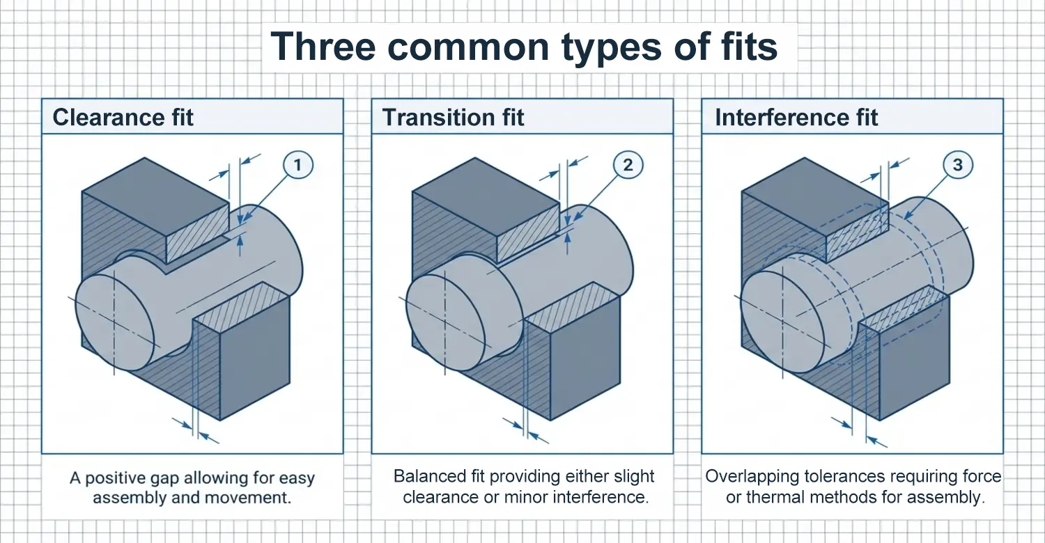
“Fit” in mechanical engineering is a dimensional relationship between two mating parts. In most cases, it’s between a shaft and a hole. A fit determines how these mating parts interact. There are three common types of fits in engineering design: clearance, transition, and interference. In a clearance fit, you always have a positive gap that allows you to assemble and move the parts. In an interference fit, there is overlapping tolerance. In this assembly, you require additional force or thermal methods. Transition fit is between the two extremes. It produces either a small or a slight clearance, depending on the available tolerance.
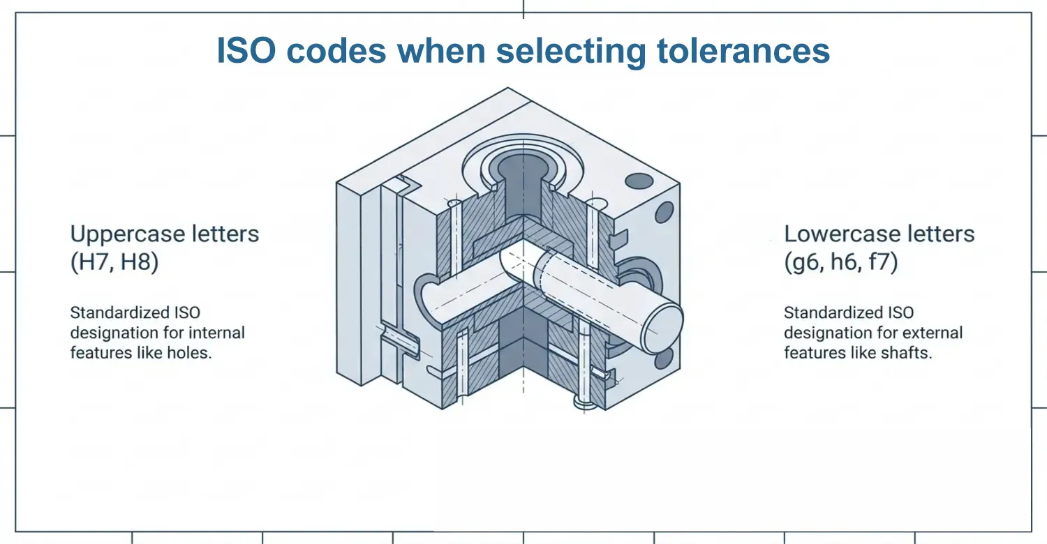
This guide discusses these three types of fits in detail, how they work, uses, and tolerance considerations. In this discussion, we will refer to a hole and a shaft even if the material is not round. A hole is an internal feature, while a shaft is an external feature.
What is Clearance Fit?
A clearance fit is the most common type of fit, in which the hole is slightly larger than the shaft, creating an intentional gap between the two parts. The gap between the two surfaces, or simply the clearance, is intentionally designed to allow free movement without friction or interference. The tolerances of both component features control clearance, ensuring a smooth fit without excessive looseness.
In design, this type of fit allows engineers to avoid forceful assembly or pressing. The shaft is smaller than the hole, allowing the two surfaces to fit effectively.
Measurement of Clearance Fit
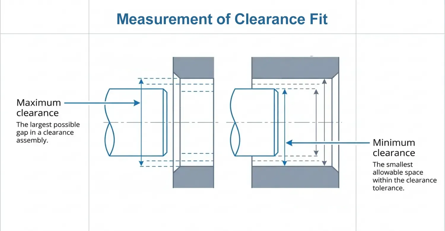
Clearance fit is measured by micrometers or callipers. Using these tools, you can determine the maximum and minimum clearance. The maximum clearance is the gap between the largest hole and the smallest shaft. On the other hand, the minimum clearance refers to the space between the smallest hole and the largest shaft. Clearance is measured in millimeters and is calculated by;
Clearance=Hole diameter-shaft diameter
If a hole has a diameter of 6.36 mm and a shaft diameter of 6.12 mm, then the clearance will be 0.24mm.
Tolerance Levels for Clearance Fit
When designing for clearance, you must specify tolerances for the manufacturing process to minimize errors. Tolerance levels show how much variation a clearance should have. For example, if you need a hole of 20mm and a shaft of 19mm to be manufactured with a tolerance of ±0.020mm, it means that any hole machined between 20.00mm and 20.020mm will offer clearance with any shaft machined between 19.00mm and 19.020mm. Similarly, you can machine a hole with a diameter between 19.98mm and 20.00mm and a shaft with a diameter between 18.98mm and 19.00mm.
Engineers follow specific ISO codes when selecting tolerances. These codes have uppercase letters and numbers (such as H7, H8) for holes and lowercase letters and numbers (such as g6, h6, f7) for shafts [1]. The following table summarizes the interpretation of the letters used in the tolerance specification.
| Letter | Component | Meaning |
|---|---|---|
| H | Hole | Lower deviation = 0(hole starts at the basic size) |
| h | Shaft | Upper deviation = 0(shaft’s largest size equals the basic size) |
| g | Shaft | Slightly below the basic size, giving a small clearance |
| f | Shaft | Further below the basic size than g, giving a larger clearance |
The numbers represent international tolerances (IT) grades. The smaller the number, the tighter the tolerance and the more accurate the machining. IT5 and IT6 tolerances are used for high precision. IT7 is used for general engineering precision. IT8 and IT9 denote medium precision, while IT10 and above denote coarse tolerance.
For instance, in an engineering setup, if you design a hole of 20mm and a shaft of 20mm with an H7/h6 tolerance, it means:
- The hole has an allowable positive tolerance starting from the basic size of 20.00mm.
- The shaft is manufactured near or slightly below the basic size with high precision, ensuring a reliable sliding or locational fit.
The following table shows some application areas for different clearance tolerances.
| Fit | Type | Typical Application |
|---|---|---|
| H7/g6 | Close clearance fit | Electric motor shafts, precision bearings |
| H7/h6 | Sliding or locational clearance fit | Guide shafts, pulleys, locating parts |
| H8/f7 | Free clearance fit | General machinery, easily assembled parts |
What are the different types of Clearance Fit?
There are several clearance fits as described;
- Slide fit: The shaft and hole are designed with a small, controlled clearance between them. The parts slide smoothly with each other without resistance or excessive play. Examples include guide rails and linear bearings.
- Easy Slide fit: The clearance is slightly larger than the slide fit. The sliding here is even easier. The easy slide fit allows straightforward assembly and disassembly due to the small gap available. An example is a drawer.
- Running fit: This fit is looser than a slide fit but tighter than a slack running fit. Designed for parts involved in continuous motion. An example is a conveyor belt.
- Slack running fit: It has larger clearance than a running fit. Applicable in parts with acceptable minor play or misalignment. Examples include fixtures and adjustable machine mounts.
- Loose-fitting: It has the greatest clearance. It’s suitable for applications where exact alignment is not necessary. Examples include sliding doors and panels.
What is Interference Fit?
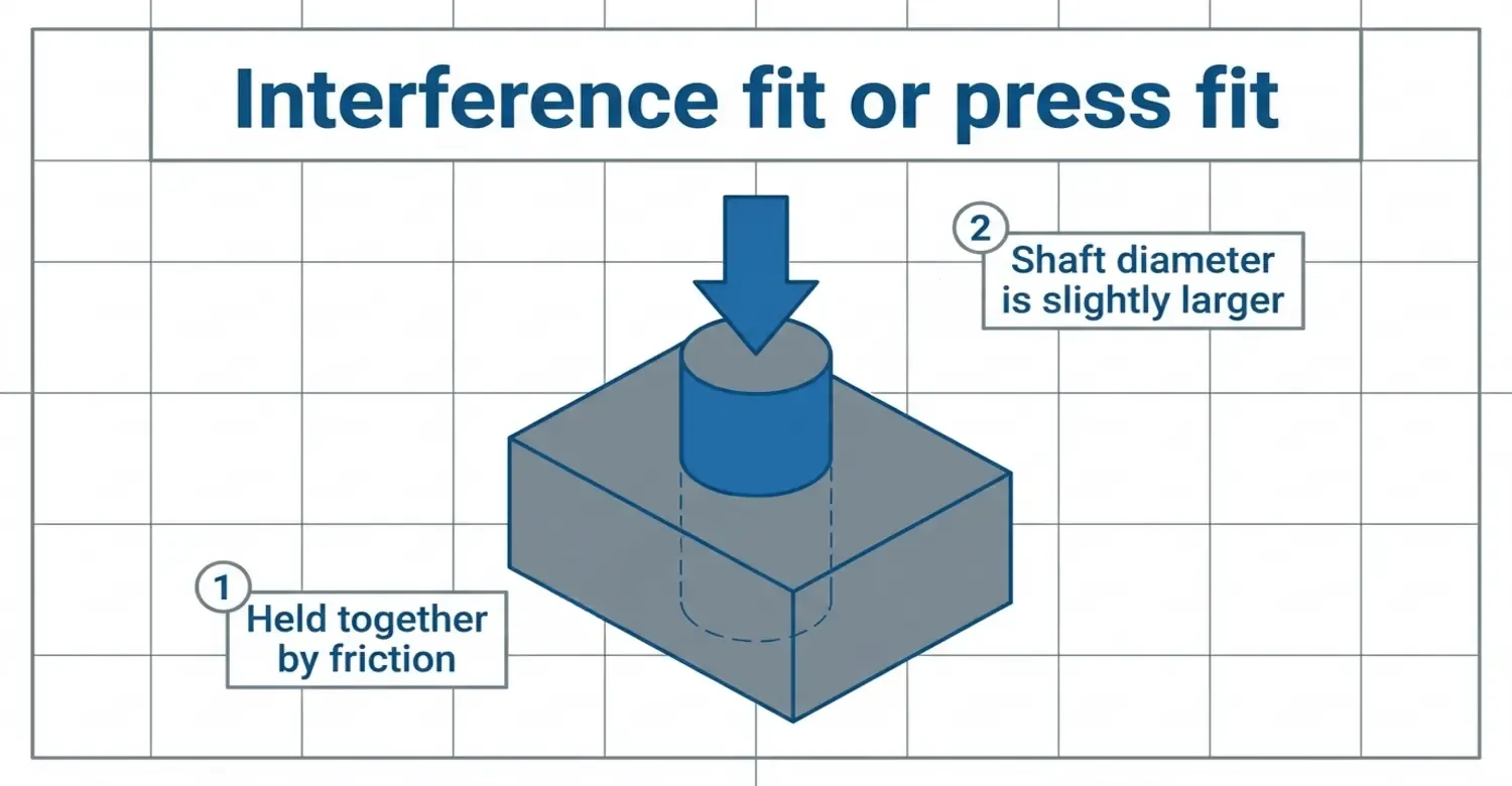
An Interference fit is sometimes called a friction fit or press fit. It is fastening between two tight-fitting mating parts that produces a joint held together by friction after the mating parts are pushed together [2]. In practical implication, the shaft diameter in this fit is slightly larger than the hole diameter. The two parts require force to join.
Interference fits form a strong, stable bond that can be permanent or semi-permanent. This fit is used in gears and pulleys, bearing assemblies, and automotive wheel hubs where components must remain fixed under stress and vibrations.
Measurement of an interference fit is similar to that of a clearance fit. However, interference is calculated as;
Interference=Shaft diameter-Hole diameter
Interference fits typically utilize tighter shaft tolerances such as s6, t6, or u6 to ensure a press-fit joint.
What is Transition Fit?
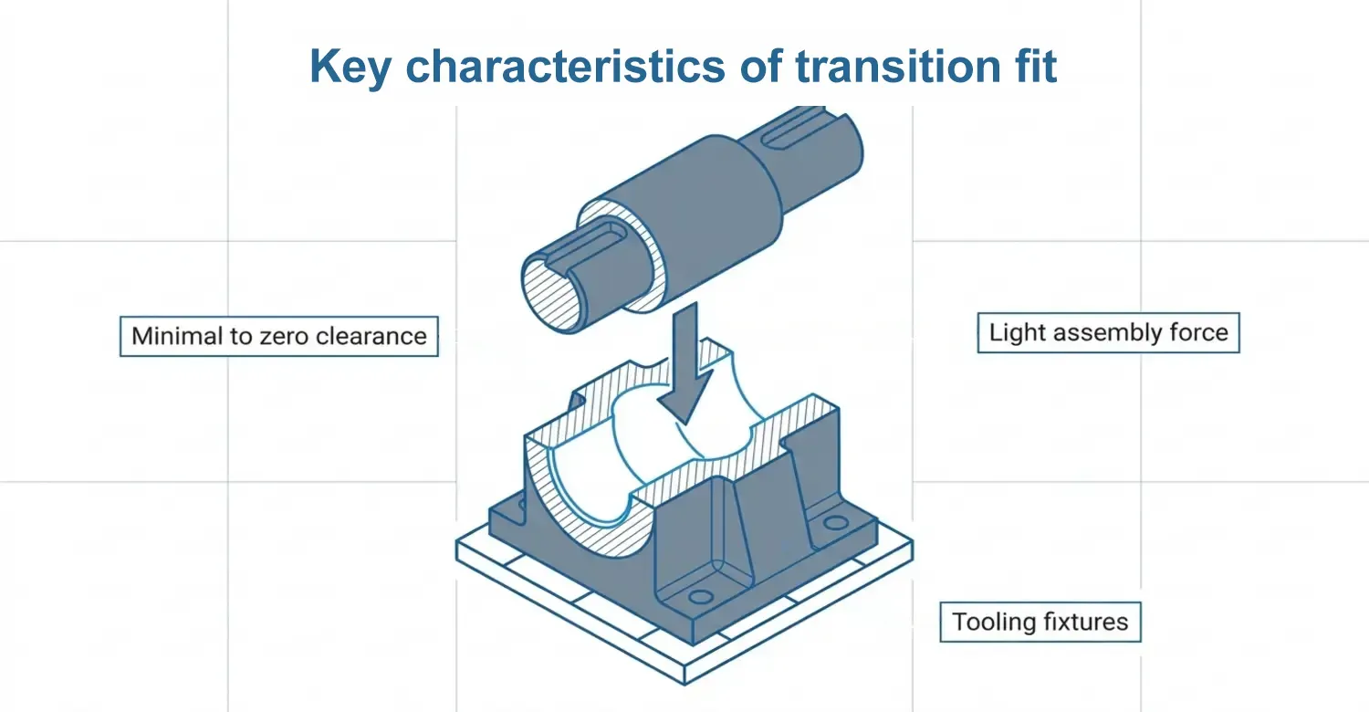
In this fit, a shaft may be slightly smaller or larger than the hole (before assembly). This fit is used to create a tight, secure connection between them in applications that require high precision and stability. It provides high accuracy, but the connecting parts can be disassembled and reassembled without damage. It allows the connecting parts to be disassembled and reassembled while effectively transmitting moderate operational loads. This fit strikes a balance between clearance and interference fits. It is used mainly where precise alignment is critical. Common applications include tooling fixtures, precision assemblies such as engine components and machinery, and bearings.
A transition fit is ideal when you need components that can be assembled by hand with light force while maintaining reasonable positioning accuracy. This fit type provides slight interference with the clearance range, making it ideal for parts that require occasional disassembly or temporary positioning.
Key characteristics of transition fit include minimal to zero clearance and light assembly force. It is suitable for manual assembly, maintains reasonable accuracy, and allows for occasional disassembly.
Industrial Application of Transition Fit
Different industries leverage transition fits for various purposes:
| Industry | Application Examples | Key Benefits |
|---|---|---|
| Automotive | Bearing carriers, wheel hubs | Easy maintenance |
| Aerospace | Guide bushings | Precise positioning |
| Electronics | Heat sinks, component mounts | Thermal expansion accommodation, serviceability |
| Medical | Instrument housings | Sterilization compatibility |
Conclusion
The “fit” is the dimensional relationship between two mating parts before assembly. Fit is critical to making sure machines and systems work efficiently and safely. Understanding the three types of fits – clearance, interference, and transition – is essential for effective product design and manufacturing. Each type serves a distinct purpose: clearance fits allow movement between parts, interference fits create permanent connections, and transition fits ensure controlled movement with precise alignment. Selecting the correct fit improves durability, simplifies maintenance, manages costs, and ensures reliable performance. Keep in mind that material properties and temperature changes play a major role in achieving the desired fit.
Reference
[1] International Organization for Standardization (ISO). (2010). ISO 286-1:2010 Geometrical product specifications (GPS) — ISO code system for tolerances on linear sizes. ISO Standards Catalog. https://www.iso.org/standard/45975.html
[2] ScienceDirect. (n.d.). Interference Fit – an overview. ScienceDirect Topics. https://www.sciencedirect.com/topics/engineering/interference-fit










 EN
EN  ES
ES  FR
FR  DE
DE  IT
IT  PT
PT  NL
NL  PL
PL  AR
AR  JA
JA  KO
KO  ZH
ZH