


CNC machining is a digitally integrated subtractive manufacturing process in which multi-axis machine tools execute computer-generated toolpaths to remove material from a workpiece with high dimensional accuracy and repeatability. The workflow begins with a parametric CAD model, progresses through CAM-generated toolpath optimization, and culminates in machine execution using standardized G-code and M-code to coordinate spindle motion, feed rates, coolant delivery, tool changes, and axis interpolation.
Process capability depends on the interaction of cutting parameters including cutting speed, feed per tooth, depth of cut, tool geometry, machine rigidity, and thermal stability to achieve target tolerances, surface integrity, and cycle-time objectives. Modern CNC environments further integrate in-process probing, adaptive machining, statistical process control (SPC), and closed-loop feedback to compensate for tool wear and process variation, ensuring consistent production quality across prototype and high-volume manufacturing while supporting advanced Industry 4.0 initiatives such as digital twins, predictive maintenance, and real-time manufacturing analytics.
CNC Machining Definition Explained
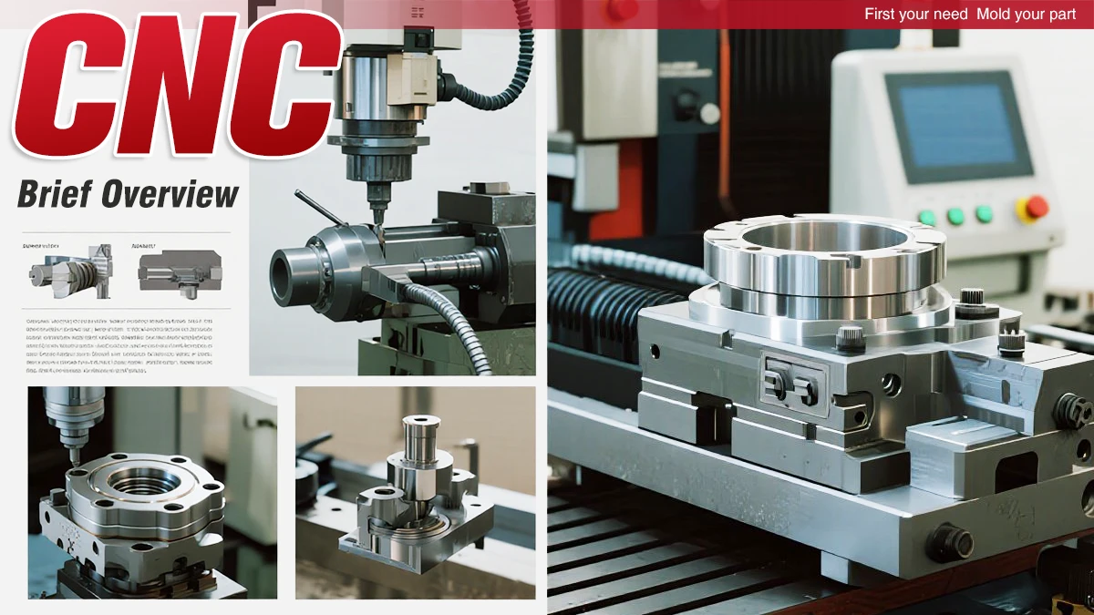
CNC (Computer Numerical Control) machining is a manufacturing method that involves the use of computer-controlled machines to remove material from a block or part in order to produce a finished piece with a particular shape and dimensions that replicates a digital design. The process is controlled by programmed instructions to move the machine, cutting parameters, and paths of the machine tools with a high degree of accuracy.
CNC describes the use of computer commands to operate machine tools such as a milling machine, a lathe machine, a router, a grinding machine, and machining centers. CNC machining uses a computer to direct a machine that cuts raw material into a finished product. The computer reads digital instructions and translates them into exact movements in multiple axes, creating the desired geometry.
Historical Background Of CNC Machining
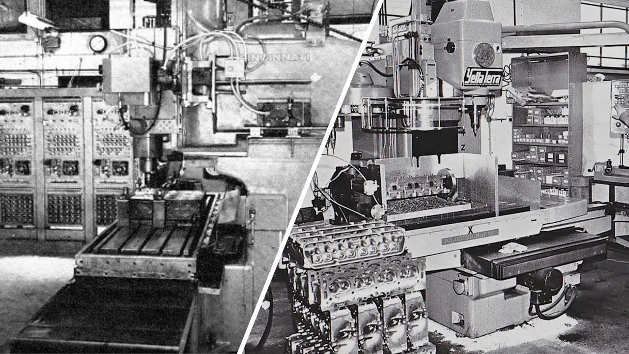
CNC machining can be traced back to the mid-1950s when numerical control systems were developed. As the parts became more intricate and complex, manufacturers required a method to manufacture them with higher accuracy than was possible by manual machining. Historically, numerical control systems were based on punched tape, and today CNC systems are based on advanced software and machine control in real time.
The main focus of the development of CNC was to increase accuracy, repeatability, and productivity. CNC systems can repeat the same program over and over with minimal variation. Humans, using manual machining, cannot replicate repeatability with little to no variation. This feature proves highly valuable in industries where precision is crucial for functionality and safety, making CNC technology indispensable.
With the continuous development of CNC technology, the positional accuracy of modern CNC machines can reach ±0.005 mm to ±0.025 mm. These tight metrics are strictly quantified and validated using international calibration protocols like the ISO 230-2 standard [1]. Ultimately, achieving such high precision is determined by the design of the machine, the accuracy of the calibration, the environment, and the process needs. Under controlled conditions, even tighter tolerances can be realized with high-precision machining centers, typically applied to manufacturing for the aerospace and medical industries.
CNC Machining Is a Digital Manufacturing Workflow: Case Study Making an L-Shaped Aluminum Mounting Bracket for an Industrial Automation System
Design
The initial step in the CNC process is design. A digital model is a creation made by a group of engineers using Computer-Aided Design (CAD) software. This three-dimensional model represents all the geometric characteristics, dimensions, and engineering specifications for the part prior to the beginning of manufacture.
At First Mold, our clients often ask us to make functional elements to aid manufacturing. To fully comprehend the various CNC machining processes, lets go through the process of manufacturing an L-shaped aluminum mounting bracket for an industrial automation system at First Mold. The finished part measures 120 mm × 80 mm × 10 mm and includes two mounting holes of Ø10 mm, four fastening holes of Ø6.5 mm, a central weight-reduction pocket measuring 70 mm × 40 mm × 5 mm, and internal corner fillets of R3 mm.
The CAD model also specifies dimensional tolerances of ±0.05 mm on critical mounting features and a surface roughness of Ra 1.6 μm on the mounting face. During the design stage, our engineers eliminate sharp internal corners that standard end mills cannot machine by adding fillets, while ensuring sufficient wall thickness around the pocket to prevent deformation during machining.
Programming
The second step is programming. The software program used in Computer-Aided Manufacturing (CAM) is used to translate CAD into machine instructions called G code and M code. In this phase, engineers identify cutting tools, spindle speeds, feed rates, and toolpaths and determine machining strategies for maximum efficiency and quality.
Back to our aluminum mounting bracket, First Mold engineers import the completed CAD model into CAM software, to develop the machining strategy. In this case, they select a 10 mm carbide end mill for rough pocket milling, a 6 mm finishing end mill for contouring, a 90° spot drill, and 6.5 mm and 10 mm drills for the mounting holes.
For 6061-T6 aluminum, roughing may use a spindle speed of approximately 12,000 rpm, a feed rate of 2,500 mm/min, and a 3 mm axial depth of cut, while finishing operations reduce the radial engagement to improve dimensional accuracy and surface finish. The CAM software also detects potential tool collisions, verifies work holding clearance, and optimizes toolpaths to reduce air cutting and minimize machining time before generating the G-code.
Machining
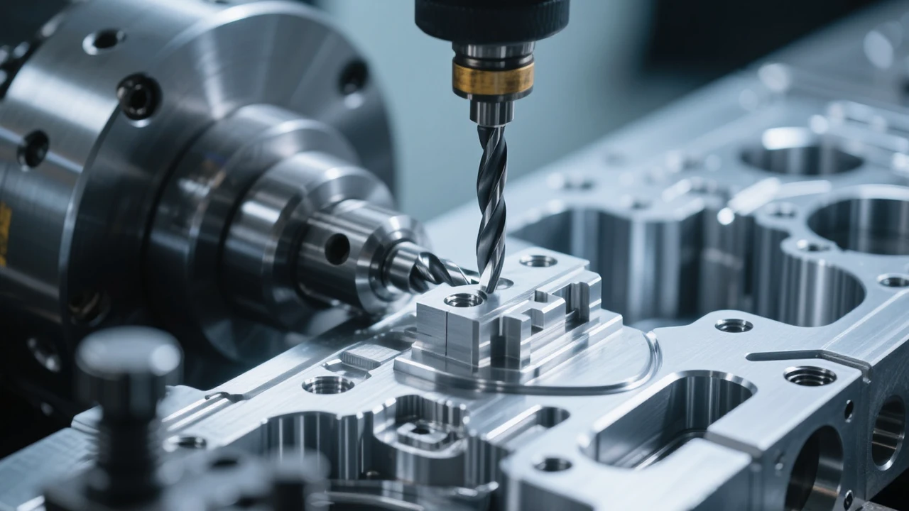
Machining is the third stage. The CNC machine follows a program to remove material from the workpiece. The typical spindle speeds are 1,000 to more than 20,000 rpm, depending on the material, the cutting tool used, the feed rates, machining conditions and the desired surface finish.
In the case of our mounting bracket, the operator secures a 130 mm × 90 mm × 12 mm aluminum billet in a precision vise, leaving excess stock for final finishing during the machining stage. After establishing the work coordinate system with a touch probe, the CNC machining center performs facing, rough pocket milling, contour profiling, drilling, and finish milling according to the programmed toolpaths.
The operator also applies coolant to control cutting temperature and evacuate chips that could damage the machined surface. If vibration or chatter develops during pocket milling, the programmer can reduce radial engagement, shorten tool overhang, or adjust spindle speed and feed rate to stabilize the cutting process without compromising dimensional accuracy.
Verification
The final stage is the verification. Manufacturers check dimensions, surface quality, and geometric tolerances with measurement instruments like coordinate measuring machines (CMMs), optical scanners, and precision gauges. The purpose of verification is to determine that the finished product meets engineering requirements.
Once machining is complete, our bracket undergoes a comprehensive inspection to verify compliance with the engineering drawing. A coordinate measuring machine (CMM) confirms the overall dimensions, hole positions, pocket depth, and perpendicularity between the bracket faces, while calibrated digital calipers and plug gauges provide additional dimensional checks.
A surface roughness tester verifies that the mounting face achieves the specified Ra 1.6 μm finish. If inspection identifies issues such as oversized holes, excessive flatness deviation, or positional errors beyond the ±0.05 mm tolerance, engineers review machining data, tool wear records, fixture rigidity, and thermal effects to identify the root cause before updating the machining program or tooling strategy for subsequent production runs.
The Role of CNC Machining in Modern Industry
Why the CNC Machining Industry Continues to Grow
The CNC machining industry is expanding globally, as manufacturers are constantly demanding greater precision, customization, and efficiency in their manufacturing processes. Products are getting more sophisticated; customers are demanding quicker delivery and greater quality.
Lack of skilled manpower in certain manufacturing industries has also led to the adoption of automation. CNC systems enable manufacturers to boost production while guaranteeing uniformity in the quality of production and minimizing reliance on manual machining.
Neto, A. & Romero, F. in their 2025 study, Perspective Chapter: Integrating Industry 4.0 and CNC Machines through CNC Tools note that with the rise of 4.0 technologies, CNC machining becomes even more important. Smart sensors, machine connectivity, data analysis, and automated process monitoring will help manufacturers to maximize production performance and minimize downtime.
Industries That Depend on CNC Manufacturing
In the aerospace sector, CNC machining is employed to manufacture extremely tight tolerances and certified quality standards of structural parts, engine components, landing gear components, and intricate assemblies. The accuracy is important since slight tolerances can impact performance and safety.
CNC machining is vital to medical device producers for diagnostic equipment, dental parts, orthopedic implants, and surgical instruments. For these products, biocompatible materials and dimension control are important to satisfy regulatory needs.
In the automotive industry, CNC systems are used to make parts for the engine, transmission, brake system, and prototype vehicles. In this sector, CNC machining also aids product development and large production.
The electronics and energy sectors also extensively use CNC manufacturing for heat sinks, enclosures, connectors, turbine parts, and renewable energy equipment.
The Cost of CNC Machining
Machine hourly rates aren’t the only factors that affect the cost of CNC machining. The comprehensive cost model includes programming time, complexity of setup, work holding, tooling usage, material usage, machining time, inspection, secondary operations, and overhead.
Key Cost: Material, Machine, and Geometry
The material removal rate (MRR) is related to the spindle power, cutting speed, feed per tooth, radial engagement, axial engagement, and tool path efficiency, all of which are influential in machining time. The production costs of difficult-to-machine alloys, like Ti-6Al-4V, Inconel 718, and hardened tool steels, are high because they require significantly lower cutting speeds. For example, while standard aluminum machines efficiently at speeds over 500 m/min, titanium alloys are physically restricted to just 40 to 60 m/min [2]. This drastic speed reduction increases cutting forces and accelerates tool wear, frequently creating the requirement for premium carbide or polycrystalline cubic boron nitride (PCBN) tooling.
Another factor that affects pricing is machine capability; simultaneous 5-axis machine centers are much more expensive per hour than standard 3-axis vertical machine centers because of the greater capital, maintenance, and programming costs.
Often, the geometry of a part is more important than the size of the part when considering manufacturing cost. Long-reach cutters are needed for deep pockets to reduce rigidity and require more than one pass in order to get the desired finish, while thin walls may require slower feed rates to prevent deflection and chatter.
Precision Requirements and Design for Cost Reduction
Semi-finishing, thermal stabilization, and further metrology in the form of coordinate measuring machines (CMMs) could be required to achieve tight tolerances of ±0.01 mm, thereby extending the production time.
The designer can achieve substantial savings in machining costs by eliminating the unnecessary tolerance specifications, standardizing hole sizes, and choosing industry-standard size cutting tools. Improved toolpaths enabled by high-efficiency milling, adaptive clearing, and automated pallet systems, can result in more significant cost savings in production settings than turning cutting speeds up.
3-Axis, 4-Axis, and 5-Axis CNC Machines
The primary distinction between 3-axis, 4-axis, and 5-axis CNC machines lies in the number of simultaneously controlled axes available during machining. A 3-axis machining center operates along the X, Y, and Z linear axes and is well-suited for prismatic components where most features are accessible from a single direction.
Although highly productive for many applications, complex parts often require multiple setups to access different faces, increasing cumulative positioning error and extending production time. Four-axis machines introduce a rotary axis, typically the A-axis, allowing the workpiece to rotate while remaining clamped in a single fixture. This capability significantly improves the machining of cylindrical components, gear blanks, manifolds, and parts with features distributed around multiple faces.
Five-axis machining adds two rotational axes, enabling simultaneous interpolation between linear and rotary movements. This allows the cutting tool to maintain an optimal orientation relative to complex surfaces while reducing tool overhang, improving chip evacuation, and extending tool life.
Simultaneous 5-axis machining is widely used for turbine blades, impellers, aerospace structural components, orthopedic implants, and precision molds, where freeform geometries would be difficult or impossible to produce efficiently on conventional machines. Beyond geometric capability, five-axis systems reduce the number of setups and improve positional accuracy by eliminating repeated fixturing. Furthermore, continuous tool motion can shorten overall cycle times by approximately 30% to 50% [3]. These systems also produce superior surface finishes by maintaining consistent cutter engagement across complex contours.
Design for Manufacturability (DFM)
Design for Manufacturability (DFM) in CNC Machining refers to the process of optimizing the geometry of a part to ensure that it can be manufactured efficiently and effectively, while still meeting its functional requirements.
Key Geometry Rules for Machinability
The initial steps of effective DFM are taken early in the product development process when one considers the accessibility of cutting tools, work-holding strategy, machine kinematics, inspection needs, and attainable machining tolerances. Radii should be included on internal corners and should be r = 1/8″ +/- 1/8″ to match the standard end mills used in the industry; if a sharp corner is being created at the inside corners, it will need secondary processes like electrical discharge machining (EDM).
Pocket depths should be limited to less than 4 times the diameter of the cutter, and unsupported thin walls should be provided with adequate thickness to withstand cutting forces and vibration during cutting unless there are special reasons for greater thickness. It is also important for the designer to avoid unnecessary undercuts and features that are not easily accessible, which will require special tooling or extra setups.
Standardization and Setup Efficiency
A successful DFM will take manufacturing efficiency into account throughout the manufacturing process. The positioning of features should be designed to minimize part repositioning, as each setup movement will add an alignment error and increase machining time.
Whenever possible, hole diameters should be equal to the standard drills, and the depth of the threads should not be so deep as to give excessive strength, but also as to provide a large amount of machining time. Datum structures should provide accurate fixturing and repeatable inspection, and geometric dimensioning and tolerancing (GD&T) should be used only where necessary to the function.
Thus, manufacturers can make better use of the process constraints in the initial design, which can shorten the manufacturing cycle, improve the process capability, reduce the rate of scrap production, and guarantee the process quality.
Products and Surface Finishes
The type of material dictates to a great extent the machining strategies and tooling that are required, the production costs, and the performance of the part. Commonly used for aerospace and automation components, aluminum alloys like 6061-T6 and 7075-T6 are known for their good machinability and high material removal rate.
Stainless steels, like 304 and 316, have corrosion resistance but have work-hardening properties that demand optimized cutting parameters. The low thermal conductivity and high chemical reactivity of titanium alloys require the use of lower cutting speeds and higher coolant pressure. Hardened tool steels, on the other hand, require high rigidity of the machine and wear-resistant tooling. Each of the engineering plastics (PEEK, Delrin (POM), PTFE, and UHMW-PE) has unique machining properties associated with thermal expansion, chip production, and dimensional stability.
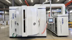
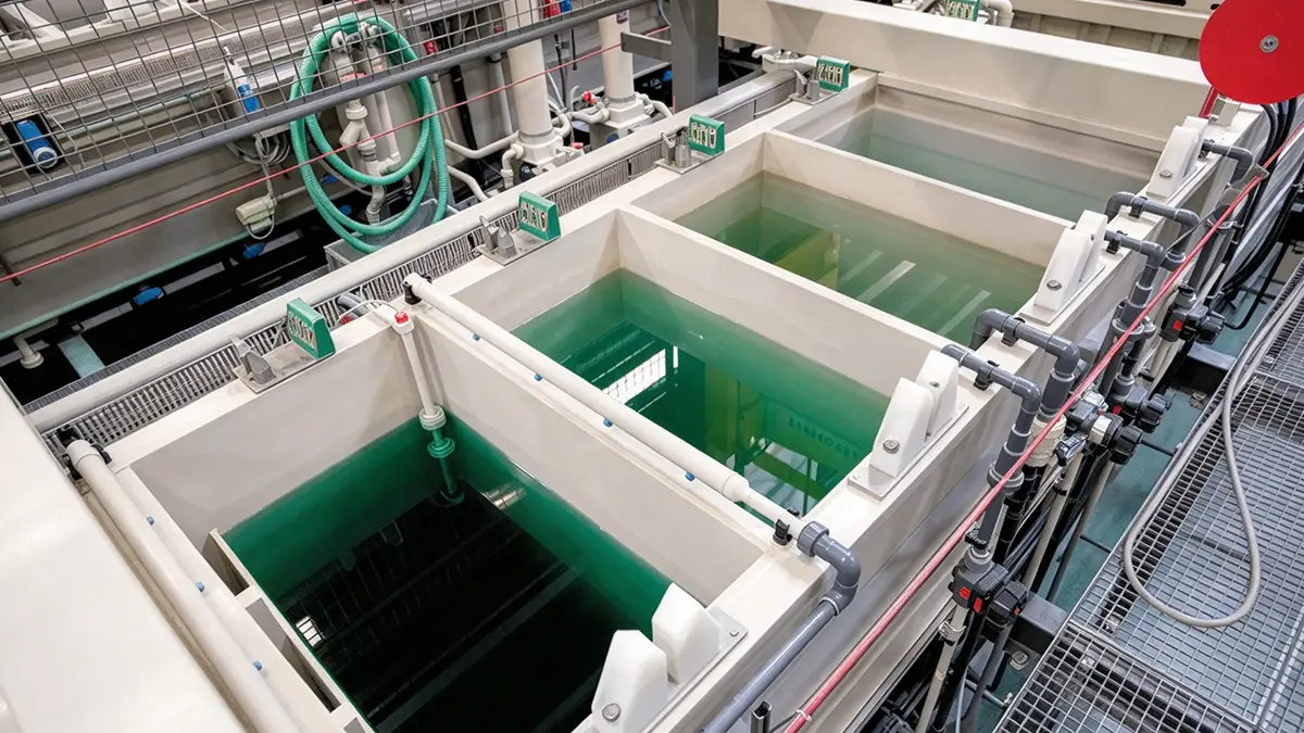
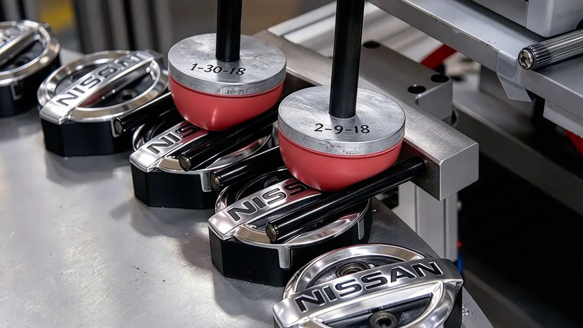
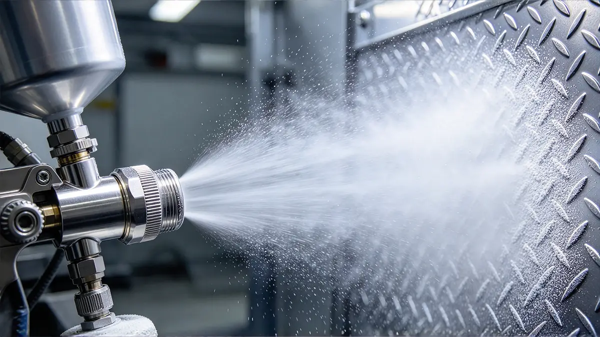
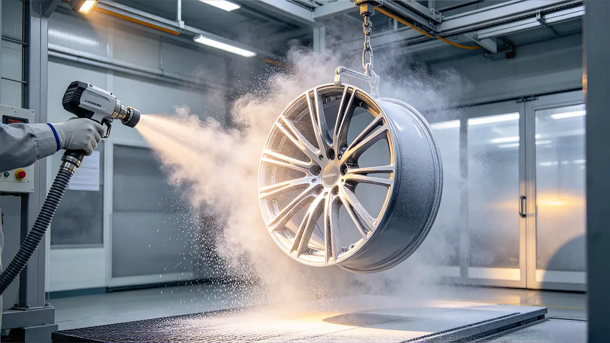
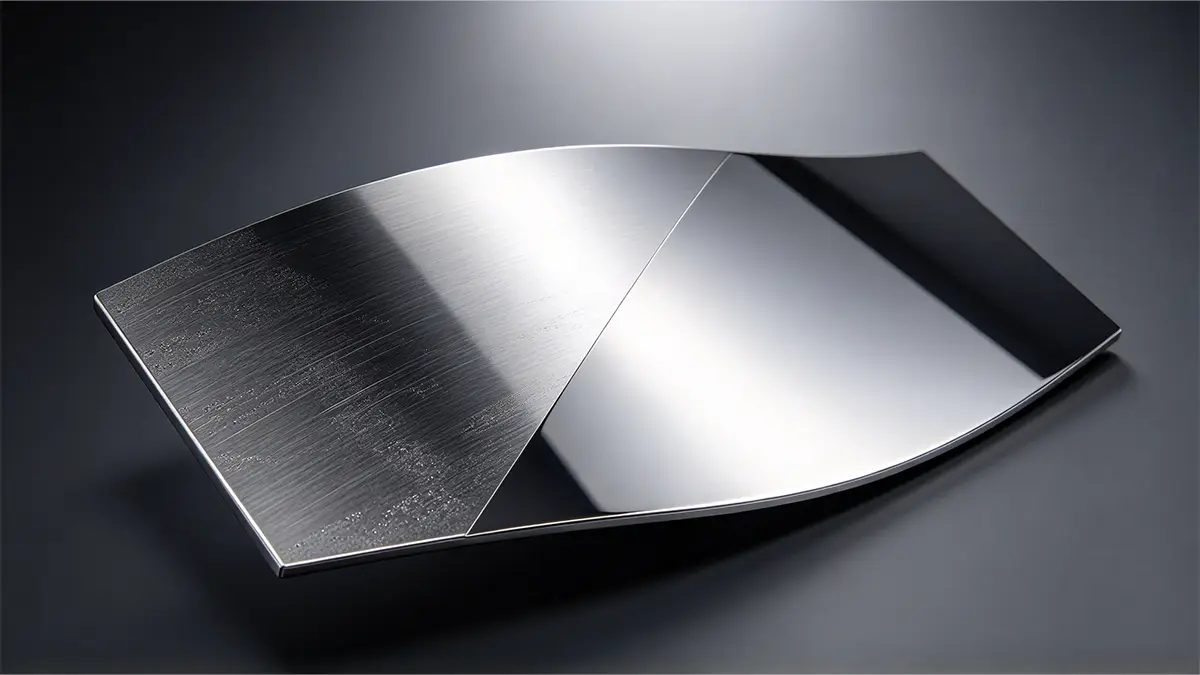
Frequent surface finishing is as important as the machining itself since it improves functional performance, durability, and appearance. Anodizing is an industry-standard process used to improve corrosion resistance and surface hardness of aluminum components and parts. Passivation or electropolishing of stainless steel parts can be used to increase corrosion resistance by removing iron contamination from the surface.
The Human Side of Automation: The Role of the CNC Worker
Is CNC Manufacturing Fully Automated?
One of the misconceptions about CNC manufacturing is that it is completely devoid of people. Although automation can accomplish numerous production operations, skilled workers are necessary for the successful machining operation.
While modern CNC system automation moves the machine and executes the processes, they still require human skills in programming, setup, troubleshooting, quality assurance, and process improvement. Advanced technology and highly trained workers are essential for complex manufacturing environments.
What Does a CNC Worker Actually Do?
CNC workers have a variety of tasks, duties, and responsibilities beyond operating the machines. They design machining strategies, identify cutting tools, write programs, design work, hold techniques, and check product quality.
They also track process performance and provide potential for optimization. There are also times when engineering judgment needs to be exercised that can’t be completely automated in terms of cutting parameters, tooling strategy, and production process.
Why Skilled CNC Professionals Remain Essential
Any manufacturing problems that could occur, like tool wear, material variation, thermal expansion, vibration, and unexpected manufacturing problems, demand human decision-making. The experienced CNC worker is able to use process data for interpretation, and can take appropriate corrective action to ensure the process remains productive and of a high quality.
With the advancement of manufacturing technology, the requirement for the individual who has a good understanding of CNC engineering, automation, data analysis, and advanced manufacturing systems is growing.
CNC Machining vs Other Manufacturing Methods
CNC Machining vs 3D Printing
There is a distinction between the use of CNC machining and additive manufacturing. The basic difference between CNC machining and 3D printing is that in CNC, material is cut from a solid block, whereas 3D printing is the process of stacking layers to create a product. The dimensional accuracy, material properties, and surface finish of the production component are typically much better when produced by CNC machining. For example, precision CNC machining consistently achieves surface roughness (Ra) values between 0.4 and 1.6 µm directly off the machine. In contrast, standard metal 3D printing methods often yield a much rougher as-built surface of 10 to 15 µm [4].
While 3D printing is excellent for rapid prototyping and very complex geometries, many functional parts need to be strong, precision-manufactured, and perform like a production part. CNC machining is still the go-to method for those production tasks.
CNC Machining vs Injection Molding
Injection molding is very efficient in the production of large amounts of plastic parts. However, this method typically becomes economically advantageous over CNC machining only when production volumes exceed a threshold of 10,000 parts [5]. This volume requirement exists because large initial capital investment and weeks of lead time are required for the development of the steel molds.
Another advantage of CNC machining is that it is more flexible, as there is no need for special molds. CNC is especially beneficial for prototypes, custom parts, low-volume production, and parts used in frequent design changes.
CNC Machining vs Casting
Casting is an economic way to produce complex cast parts at scale and large size, but cast parts need to be secondary machined to meet the final tolerances and surface finishes.
CNC machining has increased accuracy and greater dimensional stability. Casting and CNC machining are often used in tandem to deliver the best possible results, particularly in applications where accuracy and performance are paramount.
| Criteria | CNC Machining | 3D Printing | Injection Molding | Casting |
|---|---|---|---|---|
| Manufacturing Process | Subtractive manufacturing that removes material using cutting tools. | Additive manufacturing that builds parts layer by layer. | Molten plastic is injected into a precision mold cavity. | Molten metal is poured or injected into a mold and solidified. |
| Typical Materials | Aluminum, steel, stainless steel, titanium, brass, copper, engineering plastics, composites. | Thermoplastics, photopolymer resins, metal powders, ceramics, composites. | Thermoplastics, thermosets, elastomers. | Aluminum, iron, steel, zinc, magnesium, bronze. |
| Dimensional Accuracy | Very high (typically ±0.005–0.05 mm). | Moderate (typically ±0.1–0.3 mm depending on technology). | High (typically ±0.02–0.10 mm). | Moderate (typically ±0.5–2.0 mm before secondary machining). |
| Surface Finish (Ra) | Excellent (0.4–3.2 μm with finishing operations). | Fair (3–25 μm; visible layer lines often require post-processing). | Excellent (0.4–1.6 μm depending on mold finish). | Moderate (3–25 μm depending on casting process). |
| Production Volume | Low to high volumes (1–100,000+ parts). | Best for prototypes and low-volume production. | Ideal for high-volume production (10,000 to millions of parts). | Medium to high-volume production. |
| Tooling Cost | Low; requires fixtures and cutting tools but no dedicated mold. | Very low; no tooling required. | Very high due to mold design and manufacturing. | Moderate to high depending on mold or pattern complexity. |
| Design Flexibility | High; design changes only require updating the CAD/CAM program. | Very high; complex geometries require no additional tooling. | Low after mold production; design changes require mold modification. | Moderate; design changes usually require new patterns or molds. |
| Geometric Complexity | Limited by tool accessibility and cutter geometry. | Excellent for highly complex internal geometries. | Limited by mold design, draft angles, and part ejection requirements. | Good for complex external shapes but limited internal features. |
| Material Properties | Excellent; uses wrought materials with superior mechanical properties. | Good but often anisotropic due to layer-by-layer construction. | Excellent and consistent for production plastics. | Good, although porosity and shrinkage defects may occur. |
When CNC Is the Best Choice
When these factors are required in an application, such as tight tolerances, excellent surface finish, high-performing materials, and consistent quality, CNC machining may be the preferred manufacturing process. It is especially suitable for metals like aluminum, steel, titanium, stainless steel, and engineering plastics.
The process offers design flexibility as changes can be made via software and without significant tooling changes. This is a capability that helps to achieve innovation and manufacturing agility.
The Future of CNC Manufacturing: AI-Driven CNC Processing and Its Challenges
The integration of AI technologies is revolutionizing CNC manufacturing, including the ability to adapt processes in real time and optimize them ahead of time. The machining parameters optimized by AI systems are realized in real-time by analyzing machine data, thereby enhancing productivity, tool life, and product quality.
These algorithms can be developed using machine learning to predict process variations, tool wear, and maintenance needs before failure. These capabilities minimize downtime and boost manufacturing efficiency.
A 2026 study by Campean & Pop titled CNC Milling Optimization via Intelligent Algorithms: An AI-Based Methodology analyzed how large language models (LLMs), especially ChatGPT, behave when tasked with G-code optimization for improving surface quality and productivity of automotive metal parts. The study revealed that AI-generated code achieved a 37% reduction in cycle time (from 2.39 to 1.45 min) and significantly improved surface roughness (Ra—arithmetic mean deviation of the evaluated profile—decreased from 0.68 µm to 0.11 µm—an 84% improvement).
Key Challenges in Real-World Implementation
While AI is reshaping the industry of CNC machining, challenges await the integration of this technology into production. AI systems need to have a vast amount of high-quality machine data collected from sensors that measure spindle load, vibration, temperature, cutting forces, acoustic emissions, and tool wear.
Legacy CNC machines often do not have the connectivity or standardized communication protocols to reliably provide real-time data, making their integration with modern AI platforms difficult and costly. Developing a process that is reliable and repeatable in actual manufacturing conditions, where dimensional accuracy and repeatability are of paramount importance. Adjustments that are derived from AI algorithms should be within the validated machining window to prevent excessive tool wear, chatter, thermal distortion, or part nonconformance.
Long-Term Trend
CNC machining has developed from the machine tool technology to a whole digital manufacturing system. It now integrates engineering, software, automation, data analytics, and advanced production management into a connected manufacturing ecosystem.
With the further development of artificial intelligence, smart factory technologies, and digital engineering, CNC manufacturing will further become intelligent, efficient, and flexible. The capacity to machine parts accurately will not be enough in the future, as it is also important to be able to incorporate digital technologies throughout the manufacturing process.
References
[1] ISO. (2014). ISO 230-2:2014 Test code for machine tools — Part 2: Determination of accuracy and repeatability of positioning of numerically controlled axes. International Organization for Standardization. https://www.iso.org/standard/55295.html
[2] Ezugwu, E. O., & Wang, Z. M. (1997). Titanium alloys and their machinability—a review. Journal of Materials Processing Technology, 68(3), 262-274. https://doi.org/10.1016/S0924-0136(96)00030-1
[3] Altintas, Y. (2012). Manufacturing Automation: Metal Cutting Mechanics, Machine Tool Vibrations, and CNC Design (2nd ed.). Cambridge University Press. https://books.google.com/books?id=1d0LAQAAQBAJ
[4] Gibson, I., Rosen, D., & Stucker, B. (2015). Additive Manufacturing Technologies (3rd ed.). Springer. https://link.springer.com/book/10.1007/978-1-4939-2113-3
[5] Rosato, D. V., Rosato, D. V., & Rosato, M. G. (2000). Injection Molding Handbook (3rd ed.). Springer. https://link.springer.com/book/10.1007/978-1-4615-4597-2





 EN
EN  ES
ES  FR
FR  DE
DE  IT
IT  PT
PT  NL
NL  PL
PL  AR
AR  JA
JA  KO
KO  ZH
ZH