Home / Plastic Injection Molding Service
Precision Plastic Injection Molding Services
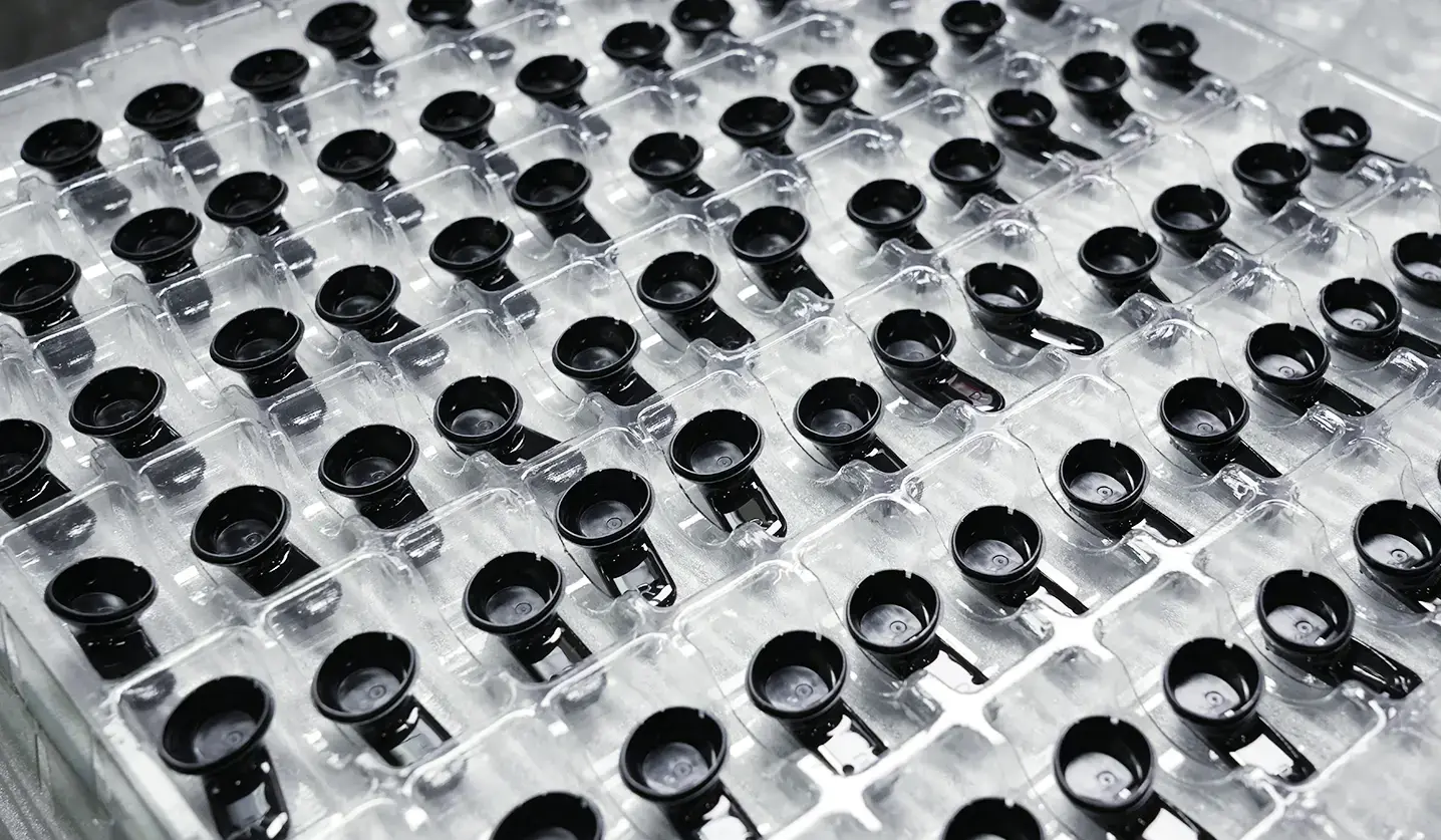
Custom plastic parts manufactured to your exact CAD specifications. Engineered with strict process controls to eliminate warpage, sink marks, and dimensional variations.
- T1 tryout samples ready in as fast as 7-15 days
- Plastic parts tolerance: ±0.05mm (±0.002")
- Comprehensive FAI Reports
Engineering Capabilities
First Mold operates over 60 advanced injection molding machines. Our parameters can support the vast majority of part production projects.
50 +
Monthly Molds Fabrication
±0.005 mm
Tooling Tolerance
| Specifications | Parameters | Specifications | Parameters |
|---|---|---|---|
| Machine Tonnage | 90T – 1000T (60+ Sets) | Production Capacity | >45,000,000 Parts/Year (>3.5M/Month) |
| Max. Dimensions (L×W×H) | 1500 x 1000 x 500 mm | Min. Dimensions | 5 x 5 x 5 mm |
| Parts Standard Tolerance | ±0.1mm (±0.004″) | Parts Precision Tolerance | ±0.05mm (±0.002″) |
| Rapid Tooling Lead Time | 7 – 15 Days | Production Tooling | 3 – 10 weeks (Automotive: 45 Days) |
| Quality Standard | DIN-7168-m / ISO 2768-m | Inspection/QC | CMM, VMS, FAI Reports |
Scalable Plastic Injection Molding Process
We build the molds and manufacture your parts entirely in-house. There are no vendor handoffs, no re-engineering, and zero dimensional errors.
Rapid Prototyping & Short Runs
Get T1 production-grade physical parts in 7 to 15 days. We use rapid tooling and scientific molding to validate your design fast.
Low-Volume (Bridge Tooling)
If your demand grows, we can often upgrade your initial quick mold by replacing only the core parts while keeping the mold base.
High-Volume Mass Production
High-volume injection molding for production parts. Hardened steel tooling built for 1,000,000+ shots, with lower unit costs as volume scales.
Advanced Molding Capabilities
100+ Plastic Materials for Injection Molding
We mold over 100 commercial and engineering-grade resins every year. Our injection molding process accommodates custom Pantone color matching, UV stabilizers, and up to 50% glass fiber (GF) reinforcement for enhanced strength.
| Common Grades | Standard, PC/ABS Blend, Flame Retardant (UL94-V0) |
| Key Specs | Shrinkage 0.4%-0.7% | HDT ~85°C |
| Typical parts | Appliance housings, decorative trim |
| Common Grades | PA6, PA66, Glass-Filled (10%-50% GF), MoS2 Filled |
| Key Specs | Shrinkage 1.0%-1.5% | HDT Up to 250°C (with GF) |
| Typical parts | Cable ties, automotive connector housings |
| Common Grades | Optically Clear, UV Stabilized, Glass-Reinforced |
| Key Specs | Shrinkage 0.5%-0.7% | HDT ~135°C |
| Typical parts | Safety guards, helmet shells |
| Common Grades | Standard, 30% GF, Flame Retardant (V-0) |
| Key Specs | Shrinkage 1.5%-2.0% | HDT Up to 210°C (with GF) |
| Typical parts | Electrical connectors, sensor housings |
| Common Grades | Unfilled, 30% Glass-Filled, Carbon Fiber-Filled |
| Key Specs | Shrinkage 1.0%-1.5% | HDT Up to 315°C (with CF) |
| Typical parts | Medical implant components, high-temperature fixture insulators |
| Common Grades | Standard Clear, Impact-Modified, UV-Resistant |
| Key Specs | Shrinkage 0.2%-0.8% | HDT ~95°C |
| Typical parts | Light guides, indicator lenses |
Surface Finishes & Secondary Operations
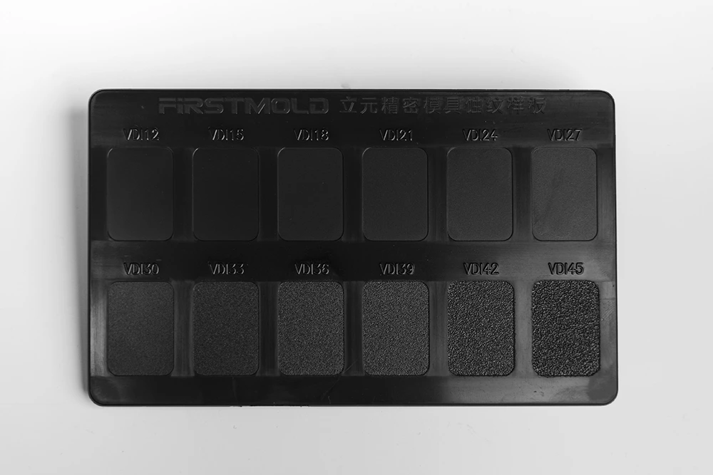
The mold shapes the part; the finish defines how it looks, feels, and performs. From in-mold SPI/VDI textures to advanced post-molding operations, we provide end-to-end finishing services to turn raw molded parts into production-ready components.
In-Mold Finishes
| Standard | Finish Category | Roughness Ra (µm) |
|---|---|---|
| SPI A1 – A3 | Diamond Buff / High Gloss | 0.012 – 0.10 |
| SPI B1 – B3 | Grit Paper / Semi‑Gloss | 0.05 – 0.32 |
| SPI C1 – C3 | Stone Finish / Smooth Matte | 0.35 – 0.7 |
| SPI D1 – D3 | Media Blast / Textured | 0.80 – 18.0 |
| VDI 3400 (12‑45) | EDM / Spark-Eroded Texture | 0.40 – 18.0 |
Need help defining the exact cosmetic or functional finish for your part? Feel free to directly Consult Our DFM Engineers for project-specific recommendations.
Secondary Operations
Coatings & Metallization
Electroplating
Gives lightweight plastics the exact look, cold touch, and extreme wear resistance of solid metal.
PVD
Provides a dazzling and scratch-resistant metallic mirror finish.
Branding & Decoration
Printing
Pad printing, silk screening, and hot stamping for multi-color graphics and warnings.
Surface Machining
Grinding & Polishing
Completely removes injection gate marks and parting lines for a perfectly smooth touch
How Do We Guarantee Zero Defects in Your Plastic Parts?
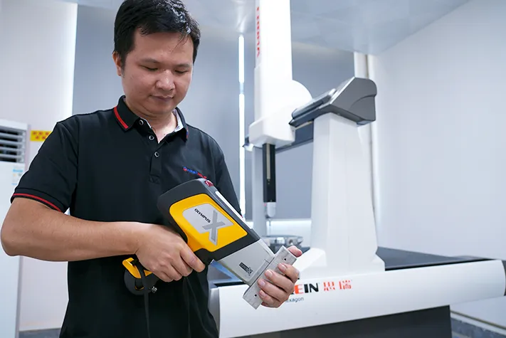
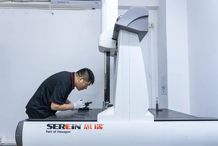
We rely on metrology and statistical process control (SPC), not guesswork. First Mold inspects and corrects critical parameters across multiple production stages.
| QA Stage | Our Methods & Equipment | Key Inspection Points |
|---|---|---|
| 1. Pre-production | Dfm Review & Mold Flow Analysis | Draft angles, wall thickness uniformity, gate locations, weld lines, sink marks, warpage prediction, shrinkage rates, undercuts, cooling channel layout, venting strategies. |
| 2. Tooling & Setup | First-article Inspection (FAI) & T1 Sampling | Dimensional accuracy, 3d cad match, material verification, surface finish quality, assembly fit, flash detection, parting line mismatch, short shots, ejector pin marks. |
| 3. In-process & Final | CMM & 2d Vision Measurement | Critical tolerances, complex geometries, gd&t (geometric dimensioning and tolerancing), flatness, concentricity, hole diameters, profile deviations, true position, perpendicularity. |
| 4. System & Compliance | Iso-certified Protocols & Traceability | Material traceability, batch-to-batch consistency, sop execution, quality control reports, resin certificate of analysis (coa), defect minimization, tool maintenance logs. |
Industry-Specific Molding Solutions & Case Studies
A closer look at how we solve complex manufacturing challenges across automotive, medical, consumer electronics, and industrial sectors using tailored resins and strict process controls.
| Industry | Engineering Focus | Featured Projects (Click to read case studies) |
| Automotive | Metal-to-plastic conversion, high-temp resistance, structural rigidity. | [Gearbox Cover], [Sensor Housing], [Dashboard Bracket], [Ignition Coil Shell] |
| Medical | Biocompatibility, tight tolerances (±0.02mm), sterilization ready. | [Surgical Tool Handle], [Ventilator Enclosure], [Dialysis Machine Valve] |
| Consumer Electronics | Thin-wall molding, SPI A2 high gloss finish, EMI shielding. | [Drone Outer Shell], [Smartwatch Bezel], [Router Housing], [VR Headset Frame] |
| Industrial | High impact resistance, wear reduction, thick-wall anti-sink. | [Conveyor Gear], [Pump Impeller], [Heavy-Duty Pulley], [Motor Housing] |
| Home Appliance | Complex assembly reduction, cosmetic surface consistency. | [Smart Thermostat Cover], [Blender Base], [Air Purifier Grille] |
Our Plastic Injection Molding Workflow at First Mold
We don’t treat your CAD files as a black box. At First Mold, our plastic injection molding process is completely transparent. Here is the exact step-by-step roadmap.
Submit CAD for Engineering Review
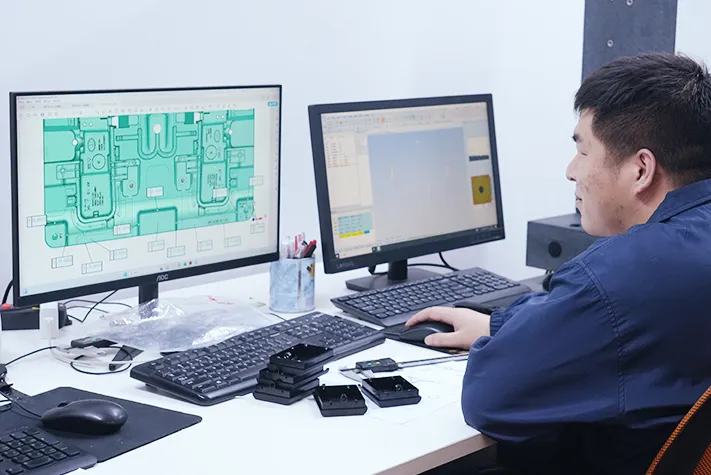
Upload your 3D models (STEP/IGES/X_T). Our engineers analyze your geometry and provide an itemized plastic injection molding quote and initial feasibility feedback within 24 hours.
DFM Approval & Mold Fabrication
Review our comprehensive DFM report detailing draft angles, shrink rates, and gating strategies. Upon your sign-off, we immediately begin CNC machining and cutting steel for your custom mold.
T1 Sampling & FAI Verification
We shoot the first physical plastics from your mold. You receive these T1 off-tool samples alongside a complete First Article Inspection (FAI) dimensional report for your engineering validation.
Mass Production & Global Logistics
Once you approve the T1 samples, we lock in the molding parameters for full-scale production. First Mold manages strict SPC quality control, packaging, and direct global shipping to your facility.
Tips: New to our quoting system? Watch this quick 3-minute demo to see exactly how to submit your CAD and get pricing: How to Get a Part Production Quote from First Mold
Recommended Structural Design Guidelines for Injection Molding
Our engineers highly recommend applying these proven structural parameters to your CAD models to avoid costly mold modifications and achieve flawless parts on the first shot.
- Maintain a uniform thickness (1.5–3.0mm). Keep variations under 20% to prevent sink marks and uneven cooling shrinkage.
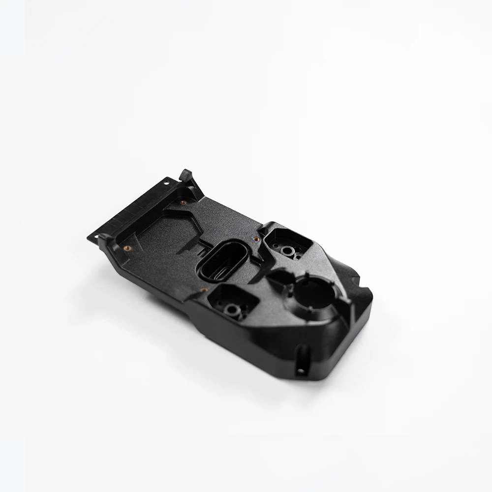
- Design internal ribs at 50%–60% of the adjacent outer wall's thickness to prevent visible sink marks on the exterior.
- Avoid sharp internal corners. Add a 0.3–0.5mm minimum radius to reduce stress, prevent cracking, and improve melt flow.
- Apply 0.5°–2° draft on vertical walls. Make the cavity draft 0.5° larger than the core to keep the part on the core during ejection.
- Locate parting lines on the part's maximum contour. Avoid high-gloss or critical assembly surfaces to minimize visible flashing.
- Design text and logos as raised (embossed). Machining recessed text into the mold steel is significantly easier and cheaper than machining raised letters.
- Limit blind hole depth to 3 times the diameter. Deeper holes risk bending or breaking core pins under high injection pressure.
- Do not attach thick bosses directly to main walls. Use connecting ribs and a coring base ("volcano") to prevent exterior sink marks.
- Keep metal inserts ≥5mm from the cavity wall. Preheat them to 80–120°C before molding to prevent thermal stress cracking during shrinkage.
- Add a 0.2–1.0mm cosmetic groove (reveal) at mating lines to seamlessly hide inevitable molding tolerances and mismatch.
- Design mating lips with 0.8–2.5mm depth and 0.1mm side clearance. Keep vertical top and bottom faces at zero gap for a stable fit.
- For reliable assembly, use 1.0–1.5mm cantilever thickness, length under 8x the thickness, and 0.3–0.5mm hook depth.
Plastic Injection Molding FAQ