

En el proceso de fabricación, el dominio de la gestión del calor determina si el componente fallará el primer día o durará años. Comprender el calor en términos de conductividad térmica y expansión térmica ayuda a los ingenieros a entender el concepto de transferencia de calor durante la fabricación de componentes. El gradiente de temperatura también es un factor importante para mostrar la diferencia de temperatura entre dos puntos de un material.
Comprender cómo interactúan estas dos propiedades ayuda a evitar problemas reales en la producción. Por ejemplo, si se elige un acero para moldes por su dureza, pero se ignora su conductividad térmica, el tiempo de ciclo se alargará. Además, si se utiliza un diseño que combina plástico y metal sin comprobar la incompatibilidad del coeficiente de expansión térmica (CTE), se producirán deformaciones o atascos en condiciones reales de uso.
Esta guía nos ayudará a comprender la importancia de la conductividad térmica y la dilatación térmica, así como su impacto en los metales y los plásticos técnicos.
Definición de conductividad térmica y dilatación térmica: ¿por qué es importante?
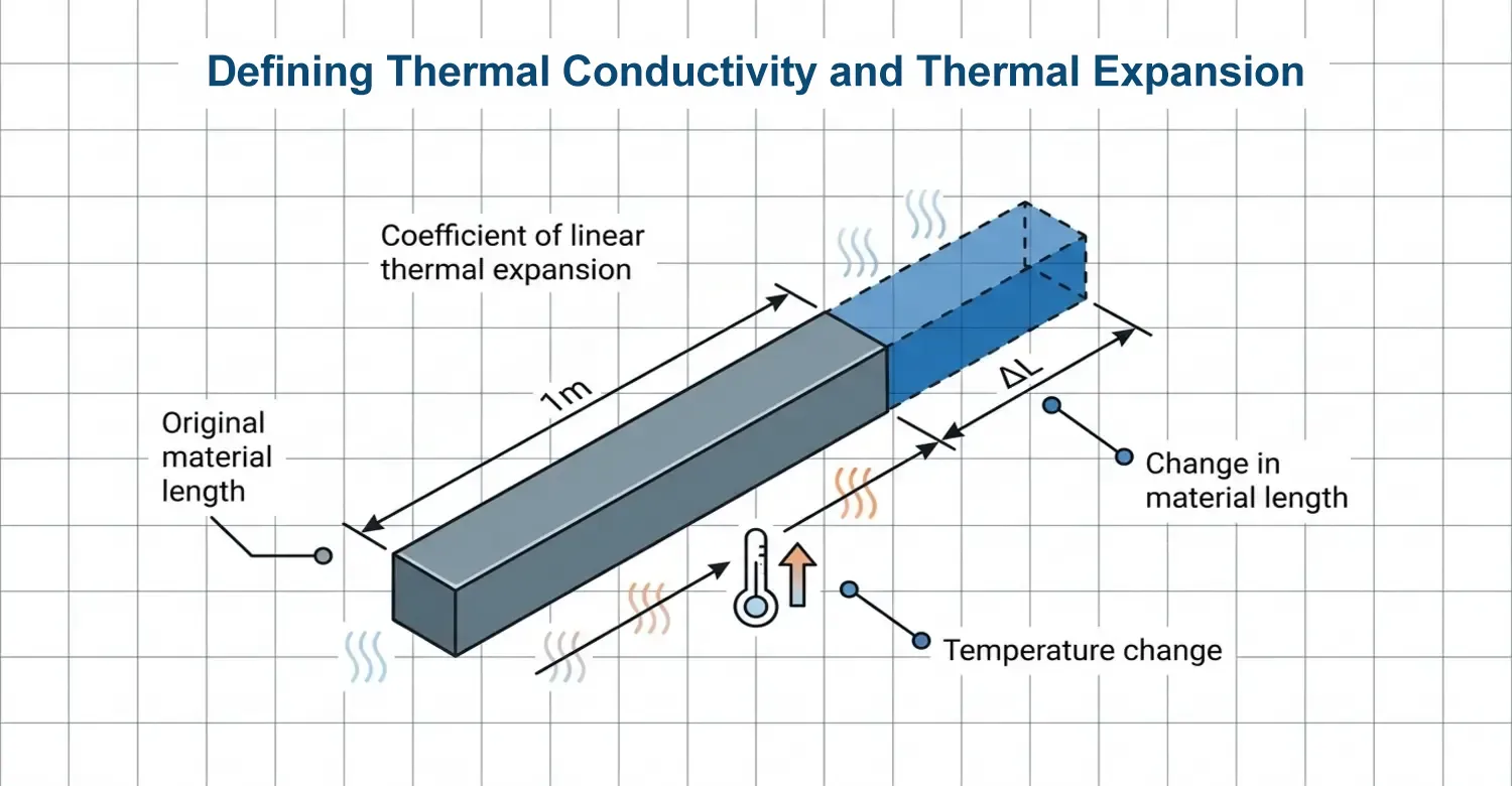
La conductividad térmica de un material indica su capacidad para transferir calor cuando se produce un cambio de temperatura. Se simboliza con (k) y se mide en vatios por metro kelvin (W/mK). [1]. En la fabricación de moldes, esta propiedad influye en los tiempos del ciclo de enfriamiento, mientras que en el mecanizado CNC, influye en la disipación del calor durante el mecanizado.
La expansión térmica describe cómo se producen los cambios de tamaño y volumen a medida que varía la temperatura. Se define matemáticamente como el coeficiente de expansión térmica lineal (CTE) (∝ = ∆L/Lθ∆T) y se expresa en unidades de ×10⁻⁶/°C, 10⁻⁶/°K o ppm/K.
∝: Coeficiente de expansión térmica lineal (CTE).
∆L: Variación de la longitud del material (L-Lθ).
Lθ: Longitud original del material.
∆T: Variación de temperatura (T final - T inicial)
Esto significa que una variación de 1 K equivale a 1 °C. Para ponerlo en contexto, 1 × 10⁻⁶/°C = 1 ppm/K. A modo de ejemplo, un CTE de 23 ppm/K significa que una viga de 1 metro de longitud se dilata 23 µm por cada aumento de 1 K en la temperatura.
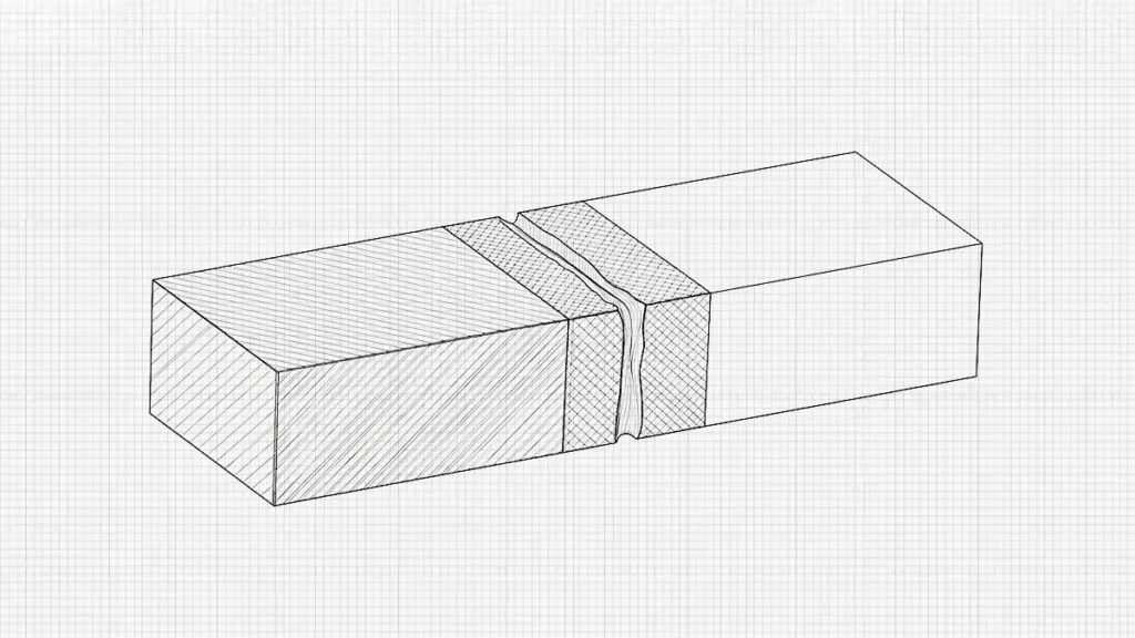
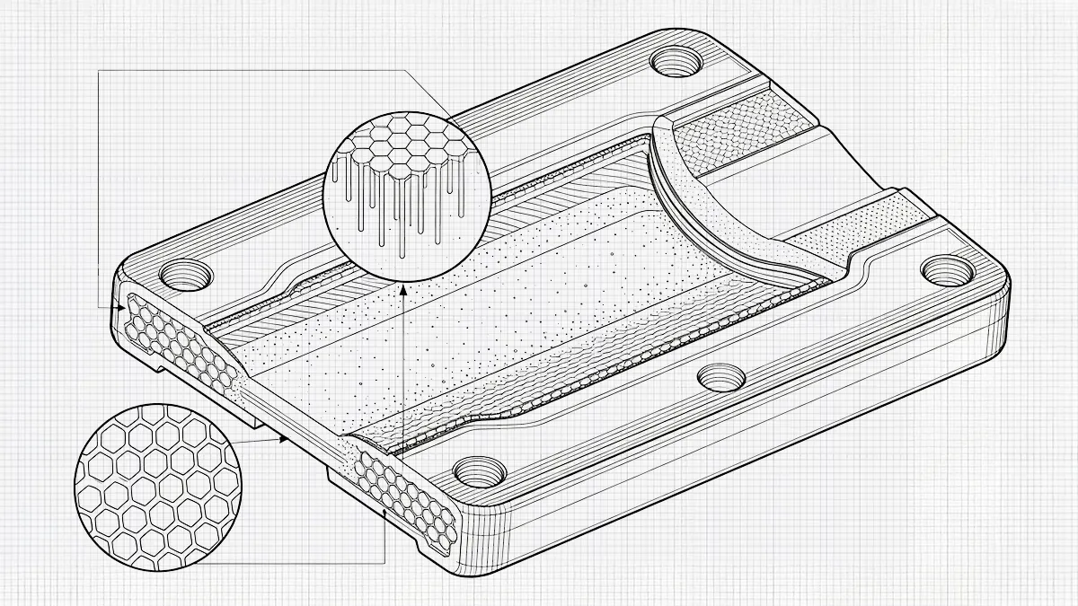
Ilustración de la expansión térmica diagonal.
El CTE resulta más eficaz en combinación que de forma aislada, de modo que dos componentes que encajan entre sí y que presentan CTE diferentes se expanden de forma distinta ante los cambios de temperatura. Este fenómeno provoca varios fallos de ajuste térmico en los ensamblajes de materiales mixtos.
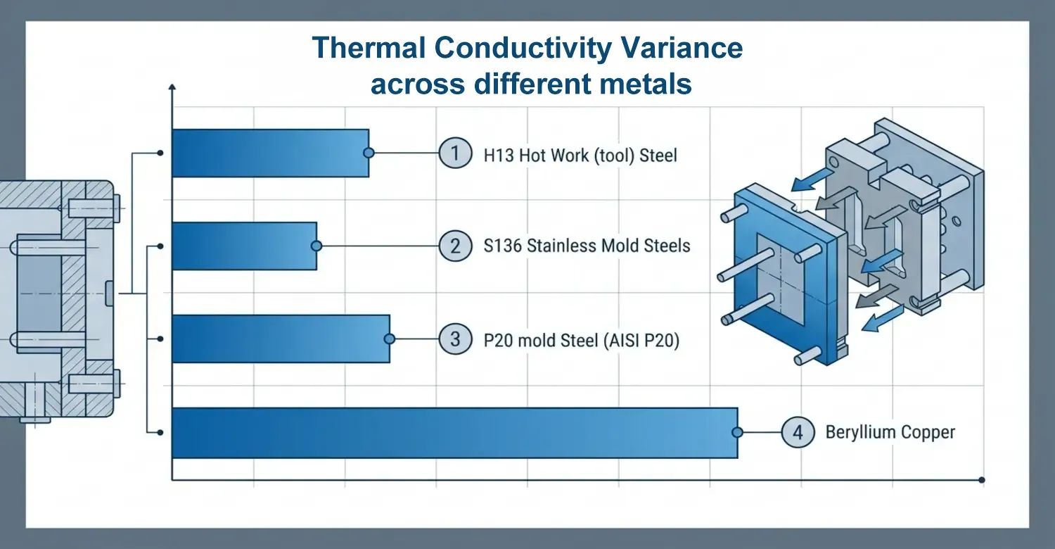
Variación de la conductividad térmica en diferentes metales, como los aceros para moldes, el aluminio y las aleaciones de cobre
Los metales presentan diferentes conductividades térmicas. Determinar las variaciones en su conductividad térmica es fundamental, sobre todo en los procesos de fabricación en los que intervienen la gestión térmica o la sensibilidad a la temperatura.
Esta tabla muestra su conductividad térmica y el papel que desempeñan en diversas aplicaciones industriales.
| Material | Conductividad térmica | Papel |
|---|---|---|
| Acero para moldes P20 (AISI P20) | ~29–36 W/(m·K), pudiendo alcanzar los 42 W/m·K en algunas olas de calor. | Plástico para moldeo por inyección de uso general. |
| Acero para trabajo en caliente (herramientas) H13 | ~24 a 34 W/m·K | Ideal para moldes de fundición a presión y de estampado en caliente. |
| S136: Aceros inoxidables para moldes (serie 420) | ~24–28 W/m·K | Se utiliza para ofrecer resistencia a la corrosión. Cavidades de calidad óptica. |
| Al7075-T6 | ~130 a 160 W/m·K | Gracias a su mayor resistencia, es ideal para piezas aeroespaciales y de automoción. |
| Aluminio puro | ~237 W/m·K | Se utiliza en moldes, plantillas y accesorios de aluminio. |
| Al6061-T6 | ~167 a 200 W/m·K | Ideal para herramientas ligeras y componentes estructurales |
| Cobre-berilio (p. ej., C17200 / TH04) | ~100–200 W/(m·K), normalmente 107 W/(m·K) | Fabrica insertos de refrigeración y pasadores de núcleo. |
| Aleaciones de cobre y hierro o de cromo y cobre | ~170 a 320 W/m·K | Insertos para moldes especializados de alta conductividad. |
| Cobre puro | ~398 a 400 W/m·K | Ideal para conductores térmicos. |
La variación de la conductividad térmica en los metales se debe a factores como:
- Estructura atómica: Los materiales como los metales conducen el calor con mayor facilidad debido a que sus redes atómicas están muy ordenadas, lo que permite el movimiento libre de los electrones.
- Densidad del material: Una mayor densidad implica una mayor conductividad térmica. Las moléculas atómicas muy compactas transfieren el calor rápidamente. La plata, con una densidad de 10,49 g/cm³, presenta una elevada conductividad térmica en comparación con el aluminio, cuya densidad es de 2,70 g/cm³.
- Temperatura: Un cambio de temperatura afecta a la conductividad térmica. Cuando se someten a altas temperaturas, algunos materiales tienden a reducir su conductividad, como el cobre y el hierro, mientras que otros la aumentan, como el silicio.
¿Por qué la discrepancia en la expansión térmica supone una amenaza mayor para la ingeniería que los valores absolutos del CTE?
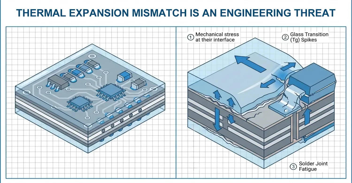
La importancia desde el punto de vista de la ingeniería de la discrepancia en el CTE se pone de manifiesto cuando se ensamblan dos materiales con CTE diferentes. Al sufrir cambios de temperatura, se expanden y se contraen a ritmos diferentes, lo que provoca la acumulación de tensión mecánica en su interfaz. Los ciclos repetidos provocan fallos en el material, grietas o fatiga térmica. En casos graves en los que se produce delaminación, pueden penetrar contaminantes o humedad y comprometer el componente.
Si tomamos dos metales como el acero y el aluminio, el coeficiente de expansión térmica (CTE) del acero es de 12,6 × 10⁻⁶/°C, mientras que el del aluminio se expande a unos 23,6 × 10⁻⁶/°C, casi el doble. [2]. Un aumento de 1 °C en un tramo de 1 metro de cada uno de ellos provocaría un desfase de 11 μm si se unieran entre sí.
Por lo tanto, la combinación de placas de molde de aluminio con pasadores guía de acero requiere que los cálculos de holgura se realicen a temperaturas de funcionamiento, y no solo a temperatura ambiente.
En el montaje electrónico, la placa de circuito impreso (PCB) y el recubrimiento conformado se expanden y contraen durante los ciclos térmicos. La expansión de una PCB de FR-4 es de 14 a 17 ppm/°C en el plano de la placa, mientras que en el eje Z oscila entre 70 y 90 ppm/°C. Se pueden utilizar diferentes recubrimientos, como el acrílico (de 70 a 120 ppm/°C), el uretano (de 60 a 100 ppm/°C) y la silicona (de 150 a 300 ppm/°C). Esto demuestra que muchos recubrimientos se expanden y entran en contacto mucho más rápido que la placa de circuito impreso que hay debajo. Esta diferencia provoca fallos específicos, como
- Fatiga de las uniones soldadas: Dado que el recubrimiento rodea las uniones de soldadura y los componentes de montaje superficial, al expandirse y contraerse con el calor, tira hacia arriba de las pequeñas patillas de los chips (como las de los BGA o los QFP), rompiendo las uniones.
- Picos de transición vítrea (Tg): Si se supera la temperatura de transición vítrea (Tg) del recubrimiento, puede aumentar el coeficiente de expansión térmica (CTE), lo que acelera la deformación mecánica.
En el moldeo con insertos, la mayoría de los componentes metálicos están encerrados en carcasas de plástico. Los insertos roscados de latón cuentan con carcasas de ABS, diseñadas con una geometría de separación para absorber la holgura debida al coeficiente de dilatación térmica (CTE). Esto se debe a que los plásticos se dilatan entre cinco y diez veces más rápido que los metales.
Un CTE de una sola pieza rara vez plantea problemas, ya que la variación térmica en una pieza homogénea es predecible y fácil de compensar.
¿Cómo deben los ingenieros tener en cuenta la discrepancia en el coeficiente de dilatación térmica (CTE) en los ensamblajes de varios materiales?
Los diseñadores de productos pueden afirmar que, al menos una vez a lo largo de su trayectoria profesional, se han enfrentado a problemas provocados por las diferencias en la expansión térmica. Se supone que un componente encaja perfectamente a temperatura ambiente, pero puede deformarse, agrietarse o distorsionarse cuando cambia la temperatura. Estos fallos se deben a una discrepancia en el coeficiente de expansión térmica (α).
Nuestros ingenieros tienen en cuenta el coeficiente de dilatación térmica (CTE) desde las primeras fases del diseño de los componentes, tanto en la selección de materiales como en el análisis de tolerancias y la evaluación térmica.
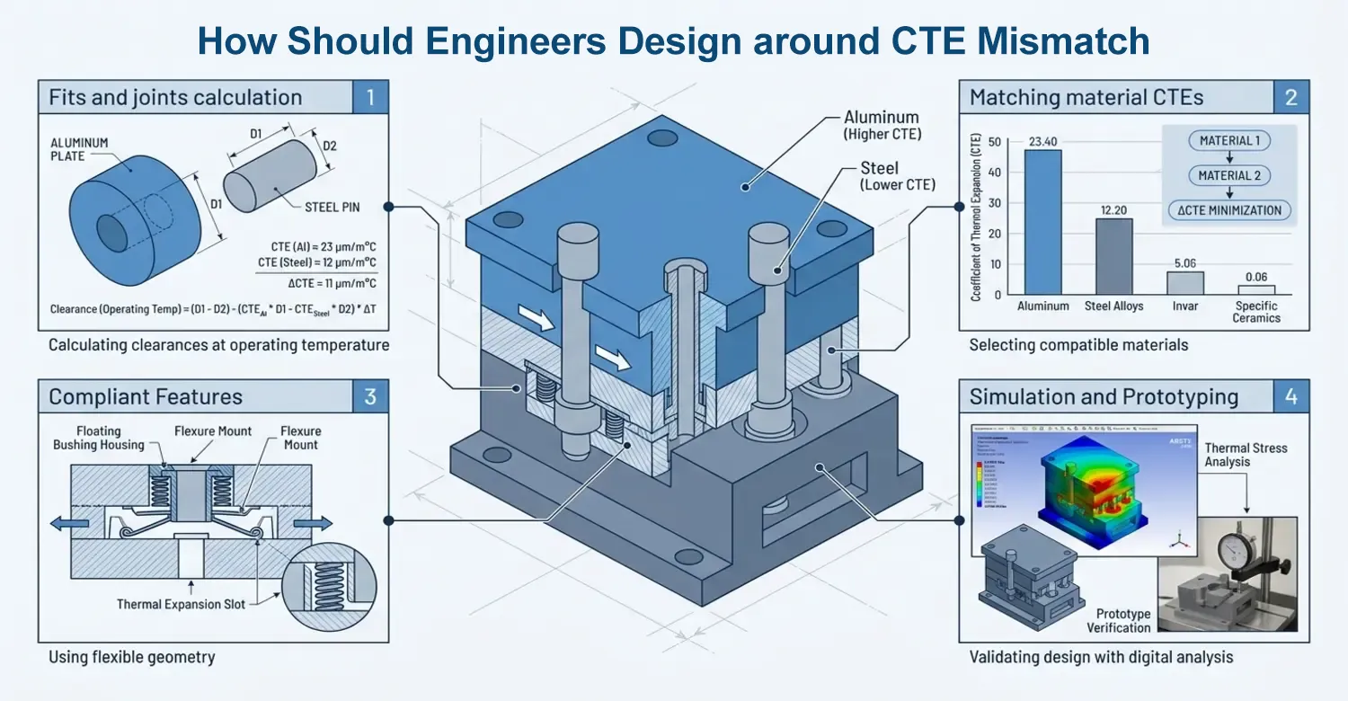
Cálculo de ajustes y uniones a temperatura de funcionamiento, no solo a temperatura ambiente
Un ajuste puede funcionar perfectamente durante el montaje a 20 °C, pero no mantener el mismo grado de interferencia a temperaturas de entre 80 y 150 °C si los materiales presentan coeficientes de expansión térmica (CTE) diferentes.
Ajustar los coeficientes de expansión térmica (CTE) de los materiales siempre que sea posible
Esta es una de las formas más eficaces de minimizar la tensión térmica en los conjuntos formados por varios materiales. Es probable que mantengan la estabilidad dimensional si se expanden y contraen al mismo ritmo. El cobre-berilio (BeCu) y el acero tienen valores de CTE casi similares; por lo tanto, las bases de molde mixtas de acero y BeCu mantienen la estabilidad en ciclos térmicos repetidos.
Características de elasticidad en las interfaces entre plástico y metal
La incorporación de geometrías adaptadas, como separadores, nervaduras o salientes, permite gestionar mejor las diferencias de expansión térmica que los insertos metálicos rígidos.
Tener en cuenta el comportamiento no lineal del coeficiente de expansión térmica (CTE) cerca de la temperatura de transición vítrea (Tg) de un plástico.
Los plásticos como el PEEK y otros polímeros semicristalinos presentan coeficientes de expansión térmica (CTE) que varían significativamente a medida que se acercan a la temperatura de transición vítrea (Tg) o la superan. Basarse en un único valor constante del CTE da lugar a cálculos de diseño inexactos.
Simulación y creación de prototipos para validar el rendimiento térmico
Los cálculos de diseño proporcionan una base sólida, pero el comportamiento térmico real viene determinado por variables operativas dinámicas. El análisis por elementos finitos (FEA) y las simulaciones térmicas permiten predecir cómo se comportará el material cuando cambie la temperatura.
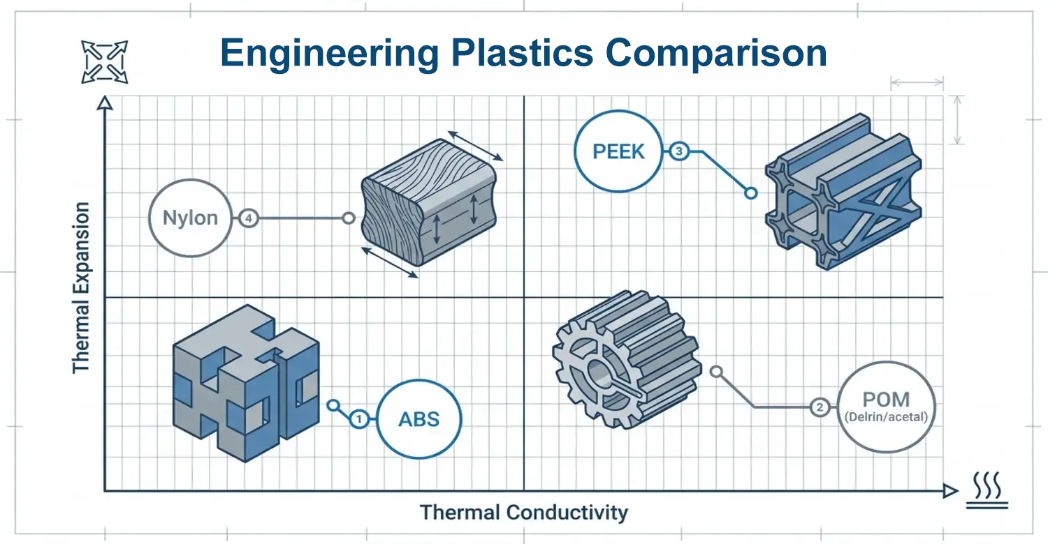
Comparación de los plásticos técnicos en cuanto a conductividad térmica y dilatación
Más allá de los metales, los plásticos desempeñan un papel importante en la fabricación; por lo tanto, determinar su conductividad térmica es igualmente importante. En lo que respecta a la conductividad térmica y la dilatación, los plásticos se sitúan en el extremo opuesto de ambas escalas. El método de fuente plana transitoria (TPS) proporciona mediciones precisas y rápidas de la conductividad térmica de un polímero. La fuente lineal transitoria (TLS) mide la conductividad térmica de los polímeros fundidos.
ABS son las siglas de acrilonitrilo, butadieno y estireno. El componente de acrilonitrilo contribuye a mejorar la estabilidad térmica del ABS. La conductividad térmica del ABS oscila entre 0,14 y 0,21 W/m·K. Las resinas CYCOLAC™, una marca de ABS, ofrecen una excelente estabilidad dimensional y un bajo coeficiente de expansión térmica lineal (CTE) entre los grados sin relleno. Por ello, satisfacen las necesidades de los consumidores en cuanto a estética y comodidad en los interiores de los vehículos y otros componentes decorativos, como rejillas, tiradores de puertas y apliques.
El POM (Delrin/acetal) tiene una conductividad térmica de 0,31 W/m·K y un coeficiente de expansión térmica (CTE) de 1,1 × 10⁻⁴ /°C. Esta tasa de expansión se encuentra entre las más altas en comparación con otros plásticos habituales. Esta propiedad lo convierte en un buen aislante térmico y ayuda a evitar la acumulación de calor.
El PEEK presenta un rendimiento excepcional en cuanto a estabilidad dimensional y térmica. Su baja conductividad térmica, que oscila entre 0,24 y 0,26 W/m·K, lo convierte en un buen aislante. Con un coeficiente de expansión térmica lineal (CTE) de 45–55 × 10⁻⁶ /°C, la temperatura de transición vítrea (Tg) del PEEK, de 143 °C, le permite soportar altas temperaturas de hasta 260 °C, por encima de la mayoría de los polímeros. Esta propiedad lo hace ideal para diversas aplicaciones de ingeniería en los sectores de la automoción y la industria aeroespacial.
El nailon tiene una conductividad térmica muy baja, que oscila entre 0,22 y 0,25 W/(m·K); por eso es mejor aislante térmico que conductor de calor. Por este motivo, resulta útil en la fabricación industrial de componentes como cubiertas de motor y colectores de admisión de aire.
Conclusión
Este artículo ha puesto de manifiesto que la conductividad térmica y la dilatación térmica van más allá de las simples propiedades de los materiales, ya que desempeñan un papel fundamental a la hora de influir en el rendimiento de los productos. Comprender cómo los materiales transfieren el calor permite a los ingenieros e innovadores crear soluciones térmicas eficaces en todos los sectores.
En First Mold, con la ayuda de fabricantes e ingenieros, abordamos estos retos desde las primeras fases del desarrollo de nuestros productos. Nuestros componentes funcionan de forma fiable en condiciones reales de funcionamiento, ya que incorporamos nuestros conocimientos sobre materiales, los principios de DFM y un minucioso análisis térmico.
Nos apasiona ayudarte a superar estos retos con la ayuda de nuestro equipo de fabricación. No fabricamos diseños que simplemente funcionen, sino que ofrezcan un rendimiento constante a lo largo de todo su ciclo de vida.
Referencia
[1] Pelleg, J. (2012). Propiedades mecánicas de los materiales. Springer. https://doi.org/10.1007/978-94-007-4342-7
[2] ASM International. (1990). Manual de la ASM, volumen 1: Propiedades y selección: hierros, aceros y aleaciones de alto rendimiento. ASM International. https://doi.org/10.31399/asm.hb.v01.9781627081610




 ES
ES  EN
EN  FR
FR  DE
DE  IT
IT  PT
PT  NL
NL  PL
PL  AR
AR  JA
JA  KO
KO  ZH
ZH