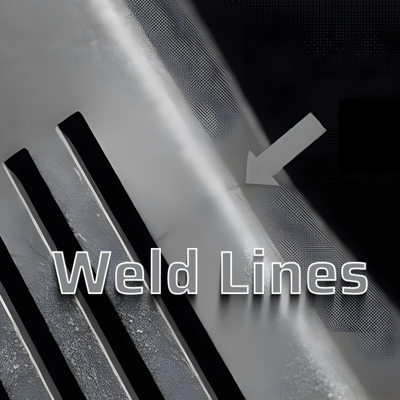
Weld lines are a common defect in molded plastic parts, affecting not only the aesthetic quality of the product but also significantly impacting its mechanical properties, especially in materials like fiber-reinforced and multiphase blend polymers.
This article provides comprehensive knowledge about weld lines. If you are interested in other injection molding defects, you can click the link below to learn more.
What Are Injection Molding Weld Lines?
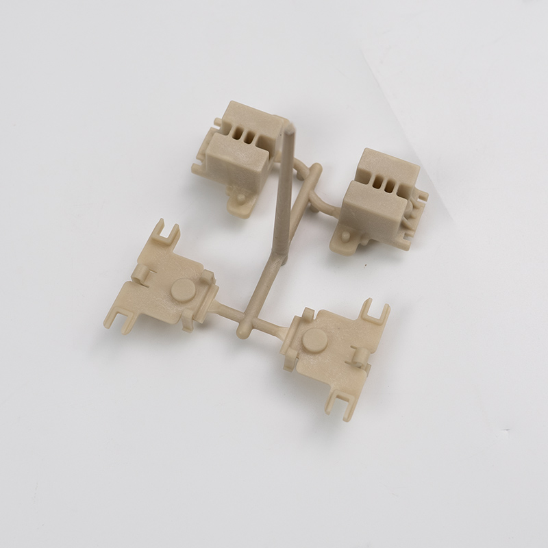
In the initial design of plastic products, unavoidable features like holes, inserts, boss posts, and changes in thickness are present. Additionally, multi-gate designs might be used in later mold designs, causing the plastic melt in the mold to flow from more than two directions. When two streams of melt meet, they form a weld line, which appears as a linear mark on the surface of the molded part.

Weld lines usually come in two types: meld lines and knit lines.
Formation Mechanism of Weld Lines In Plastic Parts
Flow Patterns of Plastic Melt in the Cavity
Before discussing weld lines, let’s briefly analyze the fountain flow pattern: the plastic melt follows the fountain flow principle in the cavity, with the fastest flow at the center and slower on the sides, resembling a fountain. Due to the effect of fountain flow, the plastic melt that first enters the cavity solidifies near the gate, with the molten core layer of the melt protruding from the solidified layers on both sides.
The formation of fountain flow: As the melt enters the cavity, it cools and solidifies upon contact with the colder mold walls, forming a thin surface layer. The core layer, insulated by the surface layer, remains at a higher temperature and continues to flow downstream of the part.
Generation of Weld Line Defects
The mechanism of weld line formation is related to the fountain flow of plastic melt. When two melt streams meet, they first contact in the middle of the section. Then they spread to the sides, and finally fill the position to form a V-shaped groove. If the air in the V-groove is hard to vent or the temperature of the two merging melt streams is too low, a noticeable weld line will form at the V-groove location.
Solutions for Weld Lines
1. From Injection Molding Processes:
| Molding Process Direction | Purpose |
|---|---|
| 1. Increase injection pressure and speed | Speed up the flow of material in the cavity, increasing the melting temperature at the junction. |
| 2. Increase holding pressure | Increase the strength at the junction, reducing weld lines. |
| 3. Increase mold temperature | Increase the melting temperature at the junction. |
| 4. Increase melt temperature | Improve material flowability and increase the melting temperature at the junction. |
| 5. Increase hot runner temperature | Increase the melting temperature at the junction. |
| 6. Thorough drying, minimal use of release agents | Reduce the small molecule and moisture content at the V-groove junction. |
| 7. Increase screw speed and back pressure | Reduce plastic viscosity, speeding up the flow in the cavity, and thus increasing the melting temperature at the junction. |
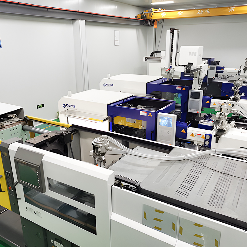
| 8. Use a larger tonnage 注塑机 | A small injection molding machine capacity, if exceeding 75% of the machine’s plasticizing capacity, may cause poor plasticization, uneven melt temperature, and insufficient injection pressure, affecting material fusion. To improve weld lines, switch to a larger capacity injection molding machine if necessary. |
2. From Mold Design
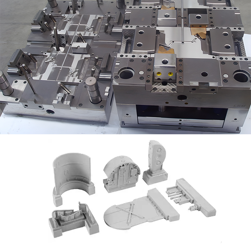
Gate System: Optimize weld lines effectively by addressing cold runners, hot runners, and gate optimization:
1). Cold runners:
Use circular or trapezoidal runners to minimize pressure loss.
Ensure cold slug wells are adequately long and transitions are smoothly connected.
Maximize cross-sectional area while keeping length minimal.

2). Hot runners:
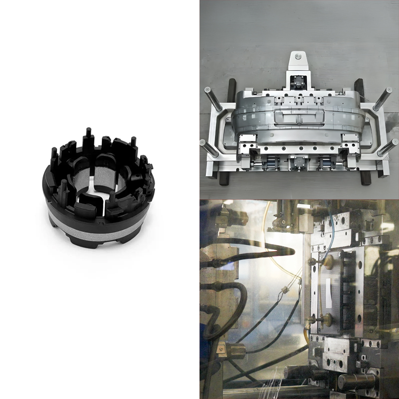
Use hot runner sequence valves for sequential gating, which can effectively hide weld lines. For example, as shown in the picture below, pin valve 2, as the main gate, opens first. After the melt front passes through 1 and 3, pin valves 1 and 3 open, preventing the formation of weld lines between gates. For unavoidable weld lines, sequential valves can sometimes successfully move the weld line to a non-visible surface. This technique is widely used in the home appliance and automotive industries where the backshell of a part uses two hot runner sequence valves opened simultaneously, resulting in a weld line formed between two gates.

3). Gates:
Avoid using pinpoint gates, sub-gates, and horn gates, which have high-pressure losses, in non-essential situations. Use gates with low-pressure losses, such as side gates and fan gates, and design gate width and thickness as large as possible under reasonable design conditions.
4). Properly arrange the number of gates:
For large parts with multiple gates, if weld lines are inevitable, increase the number of gates to reduce the flow length of the melt, thereby increasing the temperature of the melt front; for small parts, reduce the number of gates to minimize the number of melt flows.
5). Limit processes:
For unavoidable weld lines that do not meet appearance requirements, try opening exhaust slots at the fill end or, without causing flash, deepen and widen the exhaust slots.
If increasing the exhaust slots does not fully improve the situation, consider reducing iron in the mold to open overflow wells.
6). Properly arrange cooling channels:
The reasonable distance from cooling channels to weld lines is generally about 1.5 times the diameter of the cooling channel. If size and deformation are considerations, insert pieces with separate high-temperature water channels can be placed at the weld line locations, with other areas connected to normal temperature water, effectively improving weld lines. Separate water channel arrangements include: opening insert channels if space allows, or opening water wells or water towers if space is insufficient.
7). Rapid heating and cooling molds:
Connect two sets of water channels to the mold core, one for high-temperature high-pressure steam. Before injection, briefly use high-temperature high-pressure steam to raise the mold core temperature above the Tg of the material used. For cooling and setting, connect another set of water channels to cold water to cool and set the mold in a short time. This type of mold can effectively eliminate weld lines but requires high standards for molds and cooling equipment. The working principle is shown in figure 9.
3. From Product Structure
- Minimize hole features.
- Maximize wall thickness to reduce filling resistance and uneven wall thickness.
- If weld lines at boss post positions crack, consider thickening the boss posts.
- Add reinforcement ribs at weld line locations to have subsequent melt flows press the weld lines into the ribs.
- Consider weld line strength in product design to avoid weld lines in areas where strength is required.
- Adjust insert positions to change weld line locations.
- However, sometimes uneven wall thickness can cleverly weaken weld lines, as shown in the figure below.
- In mold cavities, when the molten material flow encounters ribs parallel to the flow direction, weld lines are often drawn out, commonly referred to as flow marks by clients. The example shown in the figure below proves this.
4. From Material
When switching projects or when mold and product structures cannot be changed, customers often ask suppliers to optimize material properties to improve weld lines.
- Increasing flowability is the first choice.
- Reduce the proportion of powder or additives in the material.
- For parts with hole features, avoid using paint-free materials.
- For materials with poor heat resistance, add more heat stabilizers to the formula to enable high-temperature injection molding.
Weld Line Resolution Case Study
When molding the upper cover of an electrical appliance, weld lines turned black. The material used was 个人电脑 和 ABS with a three-plate mold pin-point gate. Due to the use of pearlescent effect materials, the pearlescent color affected the appearance, so even with the maximum convergence angle, improvement was limited, and there was little room for improvement in the molding process.

Problem Analysis:
From the short-shot state, even with a large convergence angle (some even close to 180°), obvious weld lines still appeared, and the weld lines turned black, which contradicts the previously mentioned convergence angle theory. The reason is that the material used contained pearlescent pigments, which oriented and precipitated at the convergence point, causing a darkening effect. Even with a larger convergence angle, we could not improve the precipitation state of pearlescent powder at the weld line.
Solution:
In this case, by moving the gate position and opening flow channels on the back side, the weld line was moved to a non-visible surface.
When using pearlescent effect materials, consider the following to mitigate weld lines and knit lines:
- Design the shape as smoothly as possible, avoiding sharp parts and abrupt transitions.
- Use fan gates and pin valves to effectively avoid excessive weld lines.
- Ensure cold slug wells are large enough, minimize the number of gates, and shorten the process.
- Use higher mold and material temperatures during the molding process.
- When injecting in sections, ensure the melt flow speed is uniform in different parts.
- In product structural design, holes are circular and arranged along the flow direction.
- Design art slots around holes and, during design, try to ensure weld lines appear on non-visible surfaces.
In Conclusion
Weld lines are inherent in plastic injection molding. Due to product requirements, it is often difficult to eliminate them. However, with the combined efforts of product designers, mold technicians, and injection molding operators, success can certainly be achieved.
