Injection mold sliders are a very important component of mold design. Sliders and 升降机 share certain functional similarities (strictly speaking, lifters are part of the slider system). To facilitate understanding for mold enthusiasts, I will explain sliders and lifters separately. Those interested can click on the link to the lifters page to learn more about lifters.
What Is A Slider In Injection Mold
In injection-molded products, it is common to encounter many products with a large number of grooves, holes, or undercut structures. We know that during the injection molding process, after the parts are molded, the core and cavity need to be opened, and the product is ejected using ejector pins to retrieve the part from the mold. However, if the part has undercuts, holes, or grooves, it prevents the core and cavity from separating normally. In such cases, an injection mold slide is needed to assist with the demolding.
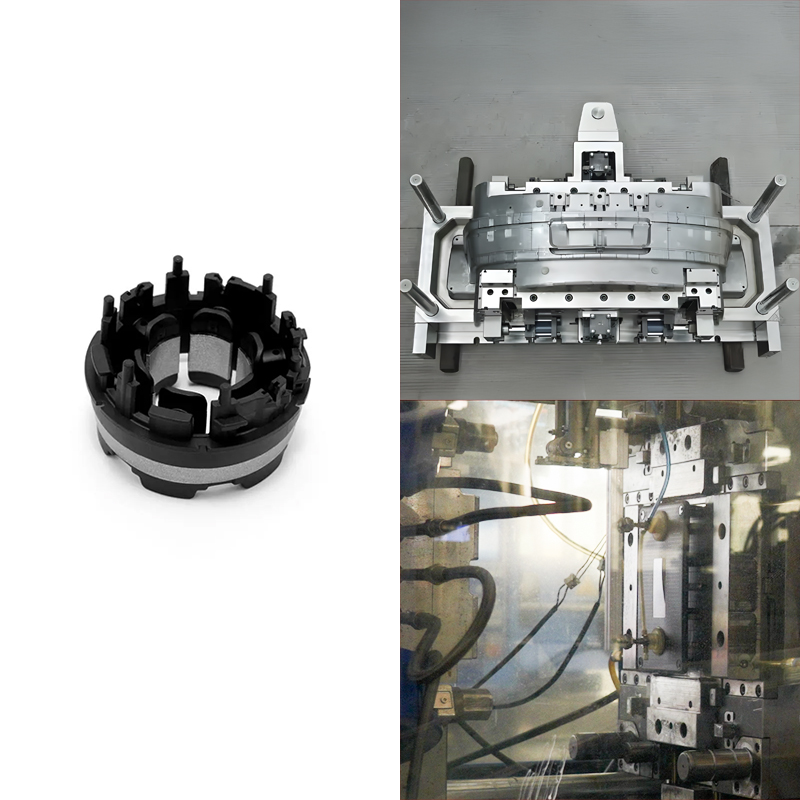
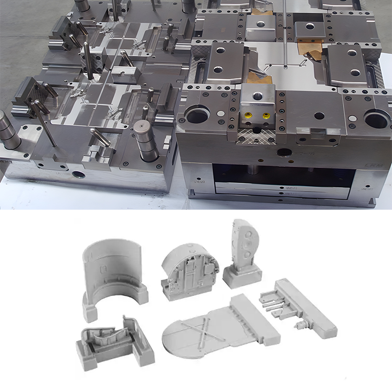
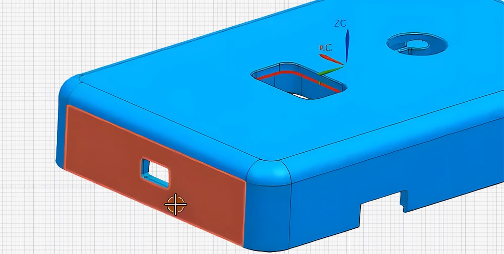
To help everyone understand, let’s take a look at the following image, which shows a part with an undercut structure on the side. This is very common in injection molded parts.
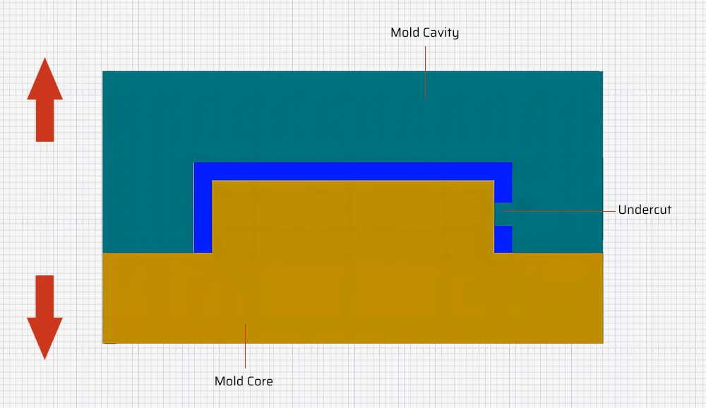
Let’s take a look at the side view of this part. The vacant area shown in the image represents the undercut structure of the part. If the core and cavity were to be separated at this point, the part would be stuck in the core and would not demold smoothly.
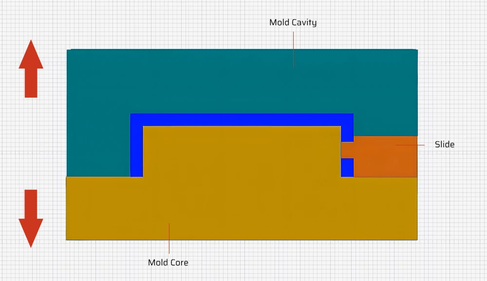
At this time, we can add a slider mechanism. The slider can be pulled out horizontally before the injection-molded part is ejected, allowing for smooth demolding. Therefore, it is not hard to see that the slider refers to a component in the mold structure that can move along the axis of the mold. It is commonly used to adjust the opening height of the mold and assist in demolding, among other functions.
The Composition And Working Principle Of The Slider
Composition
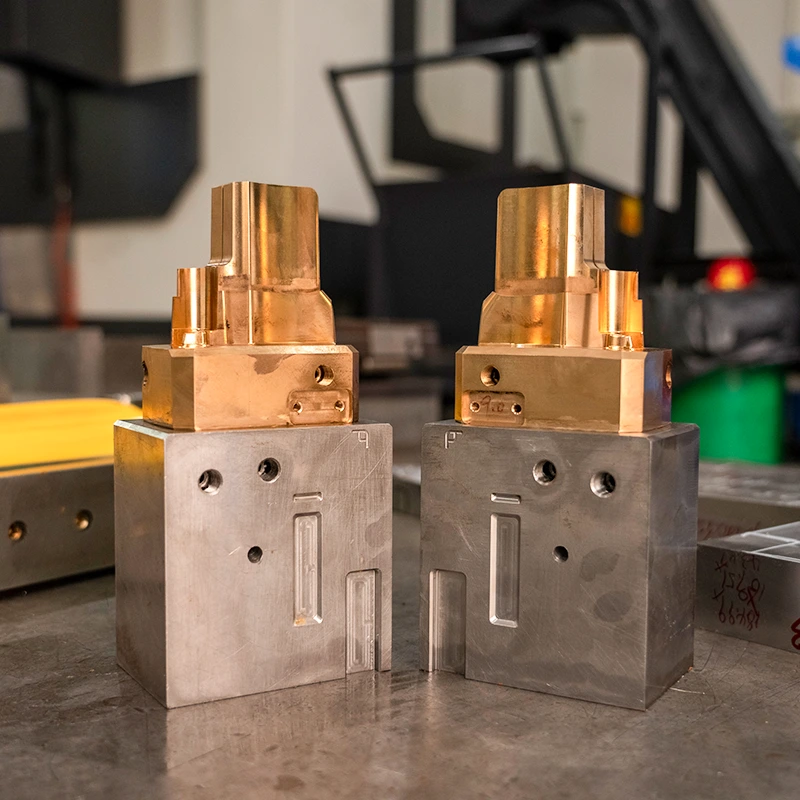
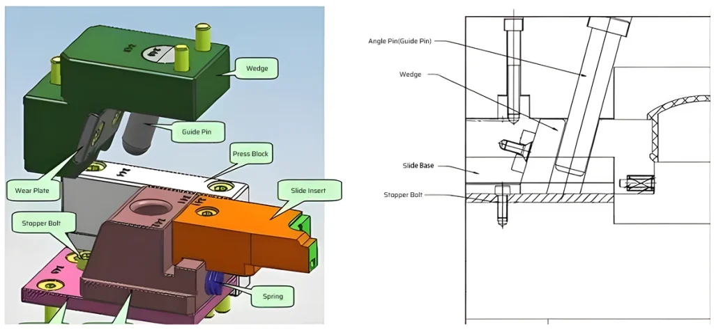
The basic components of a conventional slider include the slider base, slider insert, press block, wedge, angle pin(guide pin), wear plate, stopper bolt, and springs. Each component has its specific role.
- Slider Base: Secures the slider and bears its operational pressure and movement load, ensuring that the slider moves along the correct trajectory and stays aligned.
- Press Block: Supports and guides the upper half of the slider. It helps maintain the distance between the slide and core, ensuring the normal operation of the press and its precision.
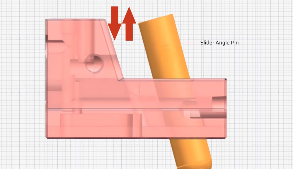
- Angle pin(guide pin): Utilizes its angled orientation to convert the vertical motion of the 注塑机 during opening and closing into the horizontal motion of the slider. This facilitates the extraction of the core from the mold cavity.
- Stopper bolt: A screw component fixed on the plastic mold slider that controls the stroke of the slider during movement, preventing excessive movement or movement beyond the designated range, thus ensuring normal operation of the mold.
- Wedge: Used to compress the slider, preventing it from retracting during injection due to the pressure of the injection.
- Slider Insert: For molded parts, especially the undercut sections of molded products, when precision requirements are strict, these sections should be separately made into inserts. This facilitates future replacement and maintenance, and they are fixed onto the slide base.
Working Principle
The slider does not have circuits or hydraulic cylinders, so where does its power come from? The power source for the slider system comes from the motion of the angled guide post. During the mold opening and closing process, the presence of the angled guide post generates friction with the inner wall of the slider. This friction force drives the entire slider system to move in a direction perpendicular to the demolding direction.
Injection Mold Slider Design Principle
Reasonable Manufacturability
The components of the slider mechanism should have reasonable manufacturability, especially the molding parts. General requirements include:
a. Avoid the formation of weld lines in the slider position as much as possible. If unavoidable, the weld line should be located in a less noticeable part of the rubber piece, and the length of the weld line should be minimized. Additionally, a composite structure should be used whenever possible, allowing the slider weld line area to be machined together with the cavity.
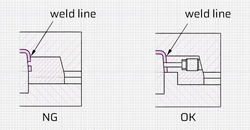
b. To facilitate machining, the molding part and the sliding part should ideally be made as a combined structure.
Sufficient Strength And Stiffness
Slider mechanisms are generally designed based on experience, and simplified calculations may also be conducted to ensure adequate strength and stiffness, generally adopting:
a. Maximum structural dimensions. When spatial positioning allows, the slider components should use the largest structural dimensions possible.
b. Optimized design structure.
1). Positioning at the end of the longer slider pin to prevent bending of the slider pin.

2). Change the structure of the wedge to enhance the strength of the assembly parts of the mold.
3). Increase locking to improve the strength of the wedge.
Slider Motion
To ensure the normal functioning of the slider system, it’s crucial that during the opening and closing of the mold, the slider mechanism does not interfere with other structural components, and the sequence of movement is logical and reliable. Several considerations are typically recommended:
A. When using a cavity slider, the sequence of mold opening should be ensured.
B. When using hydraulic sliders, the sequence of parting and returning must be controlled properly; otherwise, the slider may collide and cause damage.
C. During the mold closing, it is essential to prevent the slider system from interfering with the ejector system.
When the projections of the slider system and the ejector system overlap in the mold opening direction, it is advisable to reset the slide system to allow the ejector system to reset first.
D. When the angle pin that drives the slider is long, it is necessary to increase the length of the mold guide pin.
The purpose of extending the guide pin is to ensure that before the angle pin drives the slider system into position, the mold and cavity are fully guided by the guide pin and guide bushing, preventing damage to the slider system during mold closing.
(4) Ensure sufficient slider stroke to facilitate the demolding of the rubber parts
The stroke of the slider is generally calculated based on the depth of the lateral holes or the depth of embossments plus an additional 0.5 to 2.0 mm. For lifters, the smaller value is used, while for other types, the larger value is chosen. However, when using assembled molds to mold parts like transformer frame, the stroke should be greater than the depth of the side recesses.
Lifespan
The slider should move smoothly and reliably and should have sufficient service life.
The slider system typically employs a T-shaped guide slot for guidance.

When the slider system completes lateral parting or core pulling, the length of the slider block left within the guide slot should not be less than two-thirds of its total length. If the size of the mold plate cannot meet the minimum fitting length, an extended guide slot can be used.
The slider guide surface (i.e., the moving contact surface and the load-bearing surface) should have sufficient hardness and lubrication. Generally, the slider components must be heat-treated, with a hardness reaching above HRC40. The hardness of the guide parts should be between HRC52 and HRC56, and these parts should have machined oil grooves.
Reliable Positioning
After the slider system completes the parting or core pulling action, it should remain in the position where the motion just terminated to ensure a successful returning during mold closing. Therefore, a reliable positioning device is required, although a slider system with lifters does not need a positioning device. Below are several commonly used structural forms.
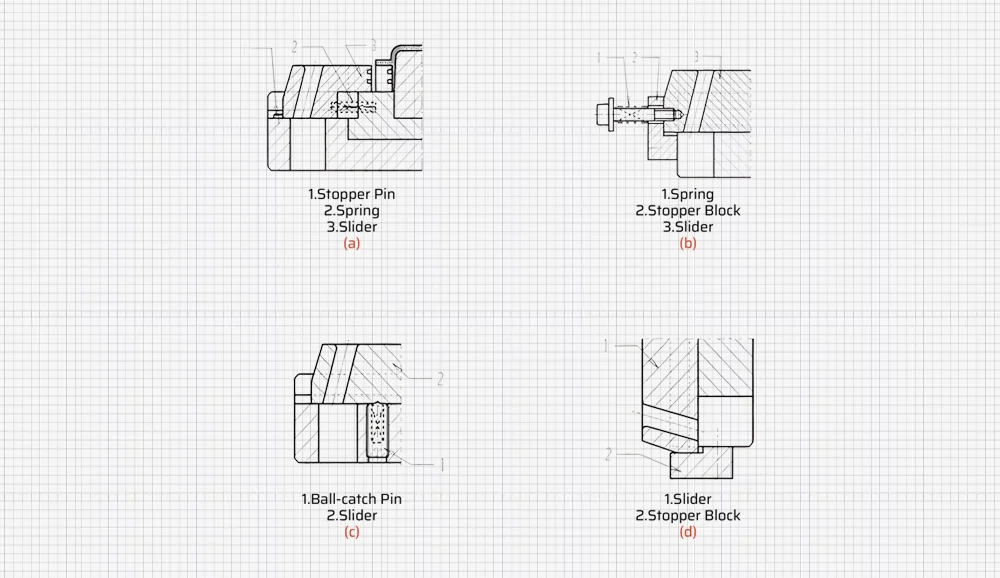
Type a): This is commonly used, but due to the limitations of the built-in springs, the stroke distance is small.
Type b) It’s suitable for molds where, after installation, the slider is positioned above or on the side and has a larger travel distance. When the slider is above, the spring force should be more than 1.5 times the weight of the slider.
Type c) It is suitable for molds where, after installation, the slider is positioned on the side.
Type d) It’s suitable for molds where, after installation, the slider is positioned below and remains on the stopper block by its own weight.
