Plastics are used in all kinds of ways in industries. They’re cheap and light, and you can use them for lots of different things. But, just like any other material, plastics have problems too. One of the biggest problems is something called “creep”. When there’s a constant force or heat acting on plastic products, creep can make them fail or work badly.
This text is going to talk about creep in a lot of detail. We want to help engineers and designers understand it better so they can use this knowledge in their work. This knowledge is really important for making sure products, like car parts and medical equipment, are reliable and safe. We’ll also put creep into different categories, look at what causes it, and talk about how we can fix it.
What is Creep in Plastic Materials?
Creep in the context of plastic materials is a deformation process whose rate is susceptible to the stress, time, and temperature applied to a plastic. Inceptive elastic deformation occurs within the initial stage of using a load and immediately reverts upon lifting the load. On the other hand, Creep carries on even under standard conditions. The situation is even more apparent in plastics because it is more sensitive to temperature change and mechanical stress.
Creep occurs in viscoelastic material, where deformation can occur continuously over time due to heat or stress. This behavior is especially evident in loading applications, including pipes, structural parts, or sealing elements under forces or fluctuations in temperature. It causes the material to elongate, sag, or warp. Hence, Creep needs to be understood to enable the safe operation of plastic parts in this environment.
Why Does Creep Happen in Plastics?
Creep in plastics results from their behavior and is associated with viscoelastic properties. Viscoelastic property means that the material behaves like an elastic solid and a viscous liquid at the same time. Traditional materials exhibit the capacity for elastic deformation under loading. If the load remains the same, the capacity for further slow and steady deformation over time is considered ‘vicious.’ This particular behavior depends on many factors, such as the amount of stress, the prevailing environmental temperature, or the kind of plastic.

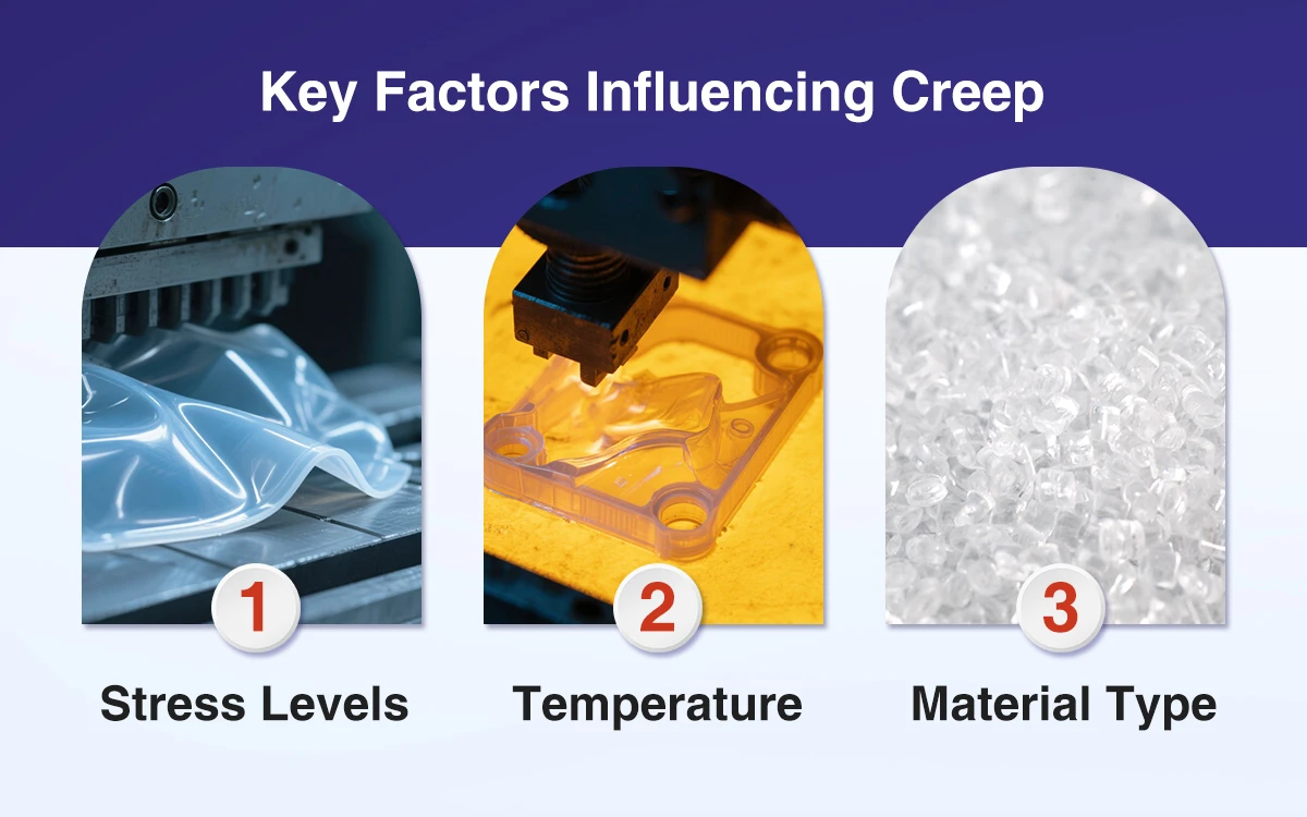
Key Factors Influencing Creep
1. Stress Levels
The extent of stress in plastic material determines the rate at which the material is prone to creep. Plastic parts, at some point, experience higher stress levels. This stress causes the molecular chains to slide past each other more easily, which leads to gradual deformation over time, rather than causing molecular bonds to break. This eventually causes rapid and more significant deformation. For example, excessive force on plastic brackets or beams causes them to sag or elongate much more rapidly than those experiencing moderate loads.
Due to its finite yield strength, the capability of the material to counteract Creep decreases when the load increases to high levels. This scenario develops the need to manage stress.
Stress also influences the increase in the production of collided internal molecular chains and the further gradual flow-through of the material. This distribution causes a loss of the structural strength of the plastic material, so in value, it is likely to fail after some time.
Engineers employ measures including spreading the load to reduce stress concentration, increasing the cross-section of the component, or selecting a more resistant plastic. Awareness of the effects of stress and Creep enables the use of plastics that will not deform quickly in some applications, focusing on the structural failure of parts.
2. Temperature
One of the critical factors of Creep is temperature. Heat generally reduces the material’s rigidity, making it more prone to deformation under mechanical stress. As the temperature rises, the molecular structure of the plastic becomes more mobile, allowing the material to deform more easily.
Plastics, in effect, alter in terms of structure when their temperature rises. The molecular structure and bonds compress, allowing the molecules to slide around. This increased mobility decreases the capacity to load stress sanely and reduces the time for Creep to happen. For instance, a plastic pipe in hot water systems is likely to sag more than a similar pipe at room temperature.
Relative to the temperature, the level of Creep can vary based on the type of plastic and its unique properties. For example, transition temperatures (Tg) and melting points determine the possibility of the occurrence of Creep. Polyethene, for example, has low Tg and is therefore deformable when subjected to moderate temperatures to form Creep.
High-performance plastics like polyetheretherketone are more resistant to heat than other forms of plastics.
There are options to manage temperature rise, such as using heat-proof material in the product design or increasing the thermal insulation component. Engineers also ensure that the operating environment temperature does not incite Creep.
3. Material Type
Different types of plastics exhibit a difference in the molecular structure. Polymers like polyethylene (PE) have weak intermolecular forces and low Tg. These materials undergo Creep more readily under static load at moderate temperatures. They have long linear molecules that can shift past one another and undergo gradual deformation.
For the same reason, engineering plastics like polycarbonate (PC) have better creep resistance due to their more ordered molecular structure and better thermal stability than standard plastics. They sustain their mechanical characteristics but stability and solidity under high pressures for long periods and increased temperatures. Thus, such materials are suitable for highly compressed uses.
Considering the variations in creep processes evidenced by various types of plastic, engineers can easily decide on the best plastics.
Measuring Creep
Engineers measure creep in creep curves. The curves show how a material changes with a regular load. Technicians obtain these curves during creep tests. A creep test is when a technician applies a definite load or stress to a material and measures the strain at regular intervals over a long period. The time ranges from hours, days, to months.

The graph that we get shows the three different stages of Creep. In the first stage, which we call the primary stage, the material starts to deform quickly at first, but then the deformation becomes stable. The second stage, or the secondary stage, is marked by a slow and steady rate of deformation. And in the last stage, the tertiary stage, the deformation speeds up really fast and finally causes the material to fail.
These curves allow engineers and researchers to understand how the material will perform after a long service. They also guide the estimation of the material’s performance under actual service conditions and make the right decisions regarding using the material in various applications.
Steps In a Typical Creep Test
The creep testing involves the following processes:
1. Applying a Fixed Load
The test first uses a constant load on a test sample of the material or stress as a percentage of the material’s yield strength. The technician applies the load precisely to exert a similar pressure throughout the sample. This load represents actual load conditions the material may experience, including bearing a static load or overcoming a steady load.
2. Monitoring Strain Over Time
After applying the load, technicians monitor the material’s ability to change shape frequently over a specified time. This monitoring can take place from hours through days to several weeks. Technicians use strain gauges during the test to monitor changes as slight as those in the material’s shape.
They maintain the temperature to be constant during the test since heat affects the flow of Creep in the test environment. This phase involves regularly measuring the material’s deformation over time to capture the changes across the three stages of Creep.
3. Creating a Creep Curve
The technicians collect and present the data as a vertical time and strain axes graph. The resulting creep curve clearly illustrates the creep behavior of the material under constant stress. Engineers can deduce various properties from this curve, including creep rate during the second stage and time to failure in the third stage. By understanding this behavior, engineers and researchers can determine if the material will meet expectations in the long term and suit certain applications, such as construction, aerospace, or automotive.

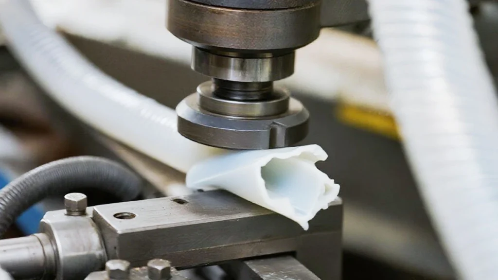
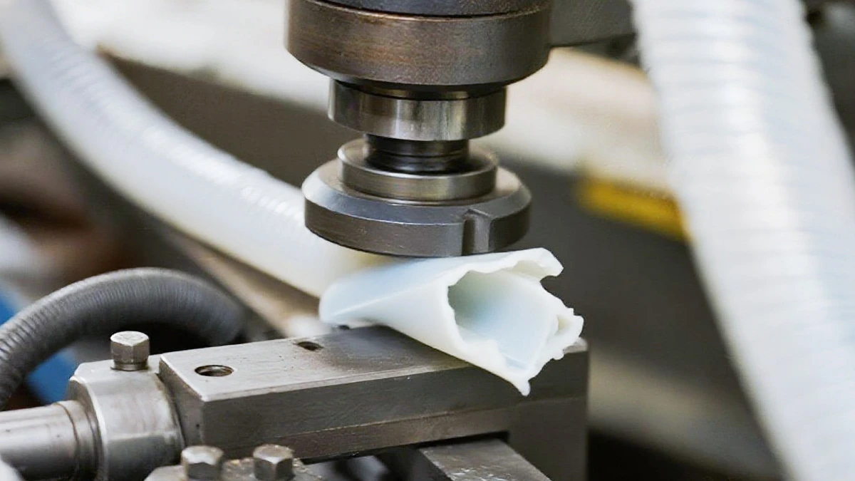
Real-World Examples of Creep
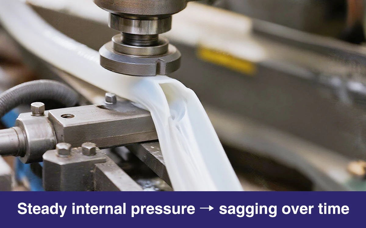
The most familiar case of Creep is identifiable in plastic pipes. They result from plastics in pipes carrying water in plumbs and irrigation channels. These pipes experience internal water pressure, which is steady, so there is a continuous load on the material. Eventually, it puts pressure on the pipes, and they can either hang or change their shape in areas where they elongate without reinforcement. High temperatures, for example, in heater systems, push the pipes to the point of elongation or failure much quicker than at average home temperatures.
Understanding the concept of Creep helps engineers to choose the right materials, such as cross-linked polyethylene (PEX).
Creep also affects automotive parts, particularly those susceptible to high heat and stress. For example, the dashboard panels and inner trims from ABS (Acrylonitrile Butadiene Styrene) look faded and lose their initial shape within a few years. These components experience mechanical stress and exposure to heat from sunlight, which looks unpleasant and interferes with operations. Automotive designers alleviate this by using heat-resistant materials, re-enforcement, or ways to modify the stress concentrations.

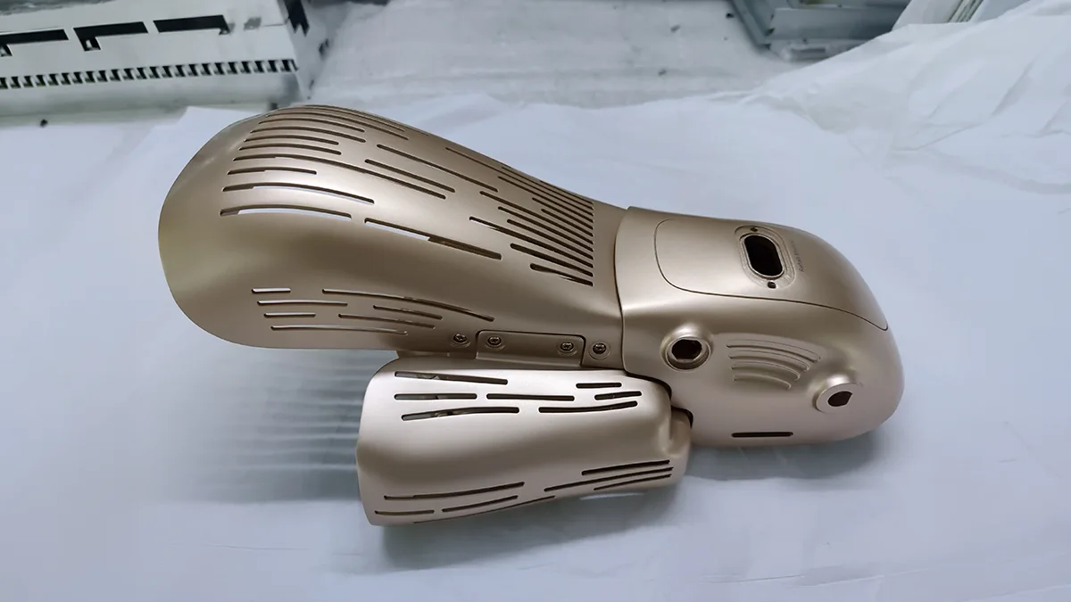
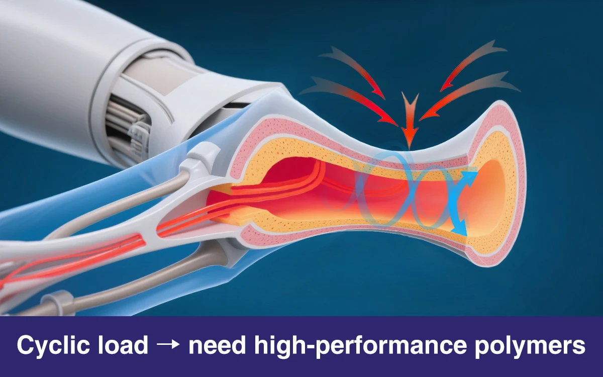
Creep is a complicated factor in medical devices since safety and reliability are critical. For instance, prosthetic devices must employ lightweight polymeric materials for the lightweight structure. These materials must keep their structure and performance stable after years of usage. Cyclic loading caused by the patient’s weight and the movements can cause the load to become gradually deformed if the material does not have high creep resistance. To manage this risk, manufacturers employ high-performance polymers such as polyetheretherketone (PEEK) to manufacture the devices. They also incorporate composites into the designs of the devices to make them more enduring and functional for a more extended period.
Design Strategies to Minimize Creep
Measures for reducing Creep in the presented plastic materials begin with material upgrading, as exemplified in reinforced plastics. Adding fibers like glass or carbon to the polymer changes its mechanical properties. These elements improve the material’s ability to withstand stress. These reinforcements make it difficult for such polymeric chains to move so that they can slide past each other in the long run. For instance, fiberglass-reinforced nylon is used mainly in the automotive industries and some industrial products. These parts have high degrees of mechanical loading.
The other management technique is reducing stress at a certain point in a component through a load-sharing approach. Stress raisers—territories with a high density of an applied force—exacerbate Creep in plastics. Engineers overcome this by avoiding sharp corners and making gradual transitions between geometries. Engineers also incorporate design features like ribs or flanges onto the load paths to increase the loaded surface area. For instance, in plastic piping systems, engineers provide the supports in such a manner that there will be minimal sagging between them. Finally, the choice of polymers with high performance is necessary for the reduction of Creep. High glass transition materials such as PEEK, polycarbonate, and PTFE have excellent resistance to deformation. These new-generation polymers usually apply under severe conditions, such as in aerospace or medical applications. These applications do not need long-term reliability compromise under pressure and heat.
Creep Behaviour Under Varying Conditions
Plastics do not always act the same way. The table below considers different environments in terms of creep rates.
| Material | Creep in Cold | Creep in Heat | Creep under UV Exposure | Creep under Constant Load | Creep in Moisture |
|---|---|---|---|---|---|
| Polyethylene (PE) | Low | High | Moderate | High | Moderate |
| PVC | Low | moderate | High | Moderate | Low |
| Polypropylene (PP) | Moderate | High | Low | High | Moderate |
| Polycarbonate (PC) | Low | Low | Moderate | Moderate | Low |
| Nylon (PA) | Moderate | High | Moderate | High | High |
| ABS | Low | Moderate | Moderate | Moderate | Low |
| PEEK | Very low | Very low | Low | Very low | Low |
| Polystyrene (PS) | Moderate | High | High | Moderate | Low |
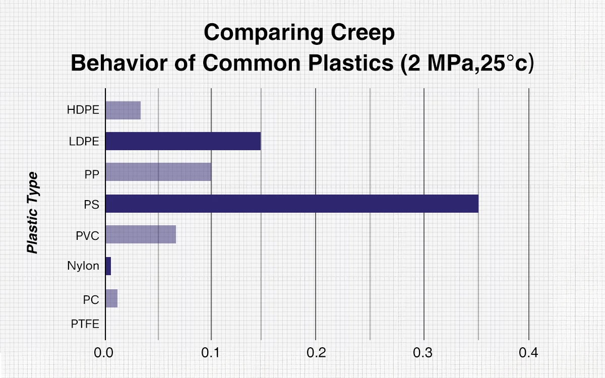
Comparing Creep Behavior of Common Plastics
The chart below shows the creep rates of several plastics having constant stress of 2 MPa at 25°C. PTFE has the lowest creep rate value, demonstrating that it can hardly deform with time. PS possesses the highest creep rate value, indicating its high tendency to deform over time.
The strength of other plastics like HDPE & LDPE, PP, PVC, Nylon, and PC vary in their ability to resist Creep and among the plastics. Both HDPE and nylon are more creep-resistant than LDPE and PS.
Conclusion
An insight into the causes of Creep, methods of minimizing its magnitude, and its effects on structures inform engineers’ choices of plastic materials. They can understand the use of plastics in industries’ applications for fabricating polymer-based components. Through proper reinforcement of plastics, adequate distribution of the loads, and correct application of high-performance polymers, engineers can go a long way to reducing the effect of Creep in their products.
Even if it is in application with plumbing, automotive, or even medical, this paper shows that engineers and designers can develop appropriate designs by making proper choices. The performance of the plastic components can increase with little compromise to creep, even under the conditions of extended time-dependent stress.