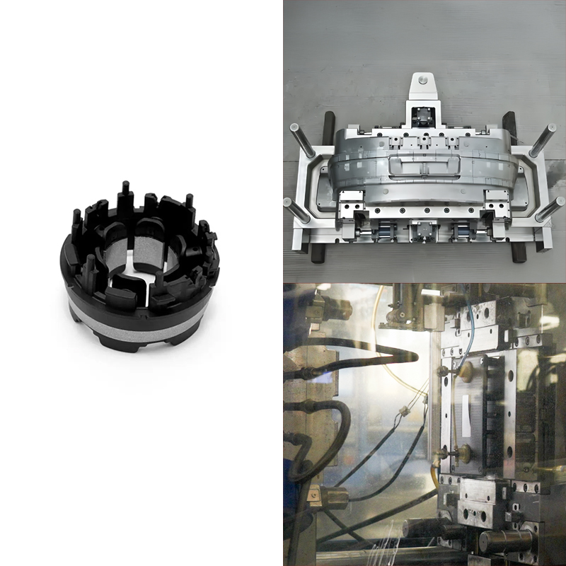
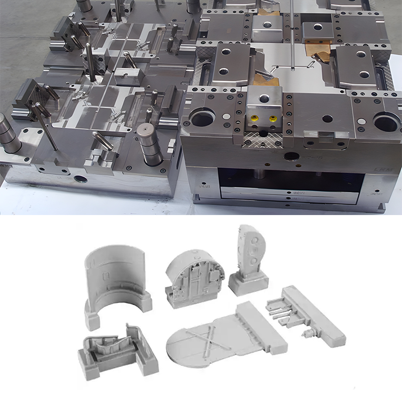
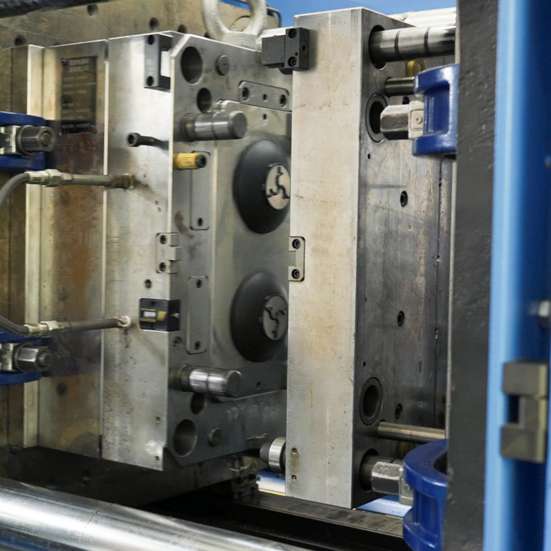
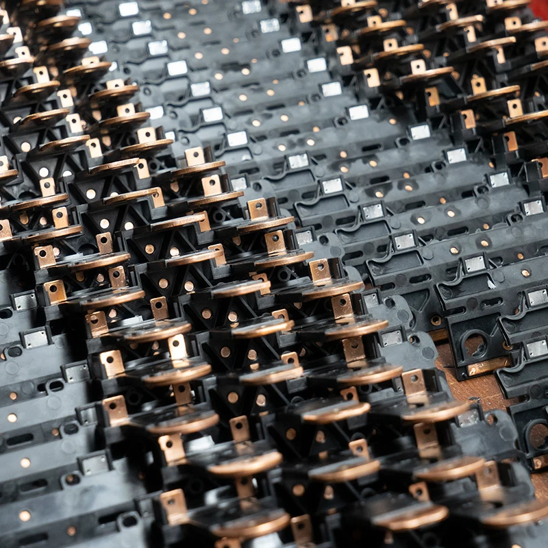
Formowanie wtryskowe involves a mass production manufacturing process of plastic parts. Their production is through the injection of molten material into a mold cavity. This process involves many molded parts with intricate structures such as podcięcia and complex designs. Removing these parts from the mold can be very challenging, thus this is where mold lifters become necessary. They are essential components to facilitate the safe ejection of the molds from the mold cavity improving part quality and overall manufacturing efficiency. The usual components of mold lifters are lifter rods, guiding pins, and the lifting mechanism. Another important element involved in part ejection is the mold slider. While they both allow movement in molds, they each have unique qualities that make them perfect for particular uses.
The major advantage of a mold lifter is that it helps to improve the efficiency of the manufacturing processes. They automate the part removal process which drastically reduces the turnaround time boosting the output without sacrificing the product quality. This not only accelerate time but also p promotes work safety. Precise and consistent part ejection reduces the possibility of damage and guarantees that every component satisfies the requirements. This enables engineers and producers to craft innovative products with intricate features, textures, and shapes that satisfy the most stringent standards of the industry.
The objective of this article is to emphasize specific facets of mold lifters like the design, selection, and drawbacks they address. This will ultimately empower our readers to make informed decisions concerning mold lifter implementation.
What is a Mold Lifter?
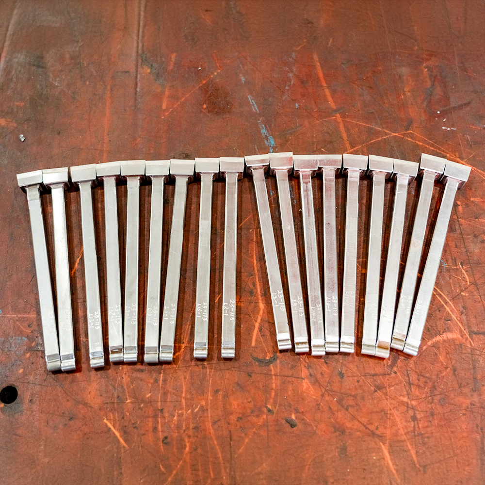
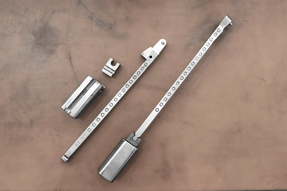
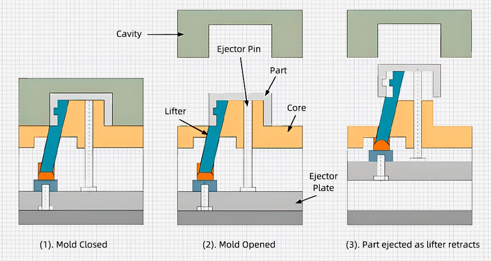
A mold lifter is a specialized mechanical component found in injection molding and die-casting. It assists in lifting and ejecting molded parts from the mold cavity once the cooling process is complete. It overcomes the challenge of removing products with complex geometry like threads, and side holes, that are difficult to release with regular standard ejector pins. Typically, comprises a mold lifter rod and a mechanism that facilitates lateral or at-an-angle movement in addition to the vertical motion of the mold.
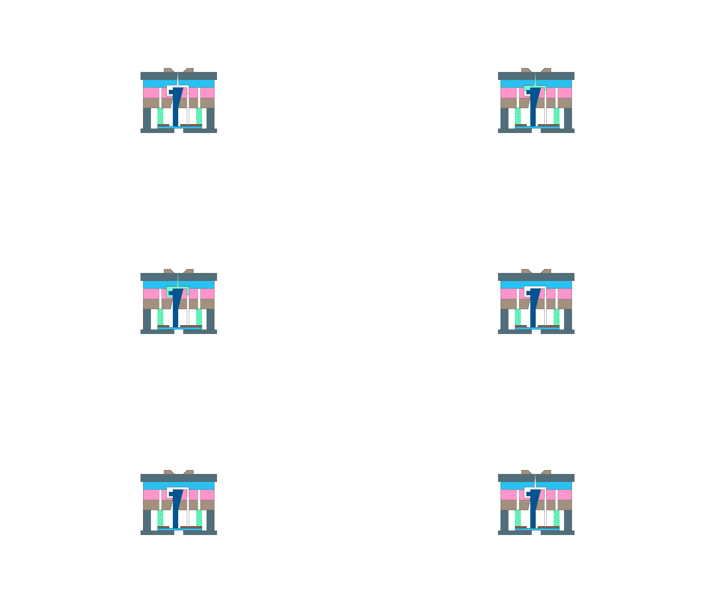
A mold lifter lies within a locating block at an angle. When activated from the bottom, it moves for a predetermined short distance to the direction of its inclination. Since there is space on top in that direction to enable the removal of the finished product, the product moves vertically when the ejection process starts. Simultaneously, the lifter moves to the opposite direction of the mold, to facilitate the release. This action makes the lifting or displacing of parts from the mold cavity effortless. Without lifters, the ejection process would be considerably more difficult, if not impossible.
An injection mold lifter has two primary components, the body and the forming parts. As a result, they are classified as either integral or non-integral. An integral lifter is typically more robust and durable from its construction. It is frequently utilized in molds for larger or more complex elements. For a non-integral lifter, an additional element adds to the mold which is not usually part of the mold’s original structure. This lifter is a bit flexible when it comes to replacement and modification. It is frequently applied in molds of smaller components where regular adjustment is necessary.
Types of Mold Lifters
A pneumatic lifter is another type of mold lifter that is applicable. This type of filter is driven by compressed air. Generally, larger molds or molds that are challenging to open with a toggle clamp get pneumatic lifters to lift.
Hydraulic Mold lifter utilizes hydraulic power to position and lift mold precisely. Suitable for handling heavy molds and complex parts.
Electric Mold lifter drive lifting mechanism through the use of electric motors. They are popular due to their efficiency, precision, and cleanliness.
Discuss how to design mold lifters.
Key components and functionalities of mold lifters.
Mold Lifter Rod
It is the main part that engages with the molded part. Its movement enables the lift and ejection of the finished product particularly those with complex shapes. The rod’s shape appears in such a way it resembles the specific geometry of the part being molded.
Guide pin
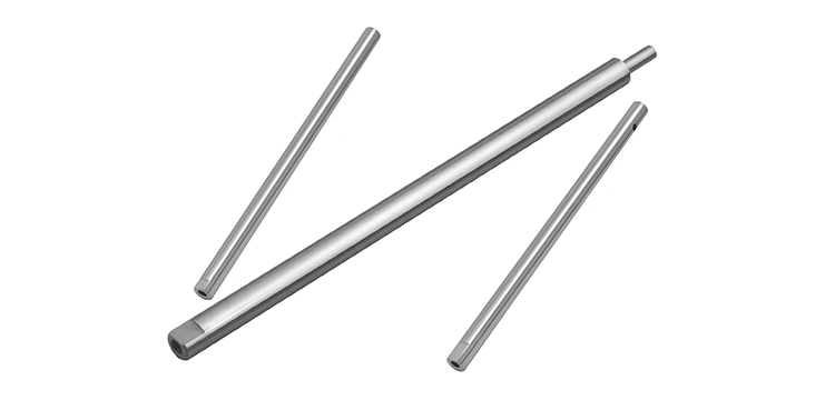
It is the component that aids in keeping the lifter rod in its proper alignment during the movement. It may consist of hydraulic systems, cams, or springs which supply the required force and motion. The lifting mechanism depends on the parts requirement since it applies to various types of motion such as; angular, vertical, or lateral.
Cam System (depends on the motion)-
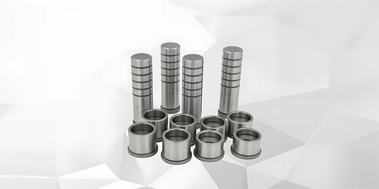
A cam system may be applicable where angular motion is necessary. The cam translates rotational motion into linear motion making the mold lifter rod move at an angle.
Return Mechanism
When the process is completed and the part is ejected, the return mechanism ensures the lifter rod goes back to its initial position to prepare for the next cycle. For this to occur there should be some components like springs, mechanical linkages, or hydraulic systems.
Ejector pins
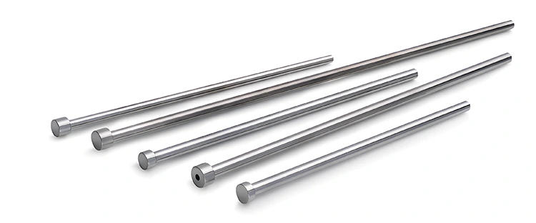
In case they are integrated into the design they push the finished part out of the mold cavity.
While the lifter offers additional force to eject the complex parts.
Housing/ Support structure.
Offer support or base to support the lifter components. Ensures all the moving parts are secured firmly and perform smoothly without sustaining wear and tear.
All these parts work together to ensure the effectiveness of the system.
Design the mold lifter.
1. Identify Part Requirements and Features
Considering the molded parts designs and specifications is necessary to ensure a smooth process. Focusing on specific features like threads, holes, or undercuts requires a special mold lifter configuration. Additionally, parts size, desired surface finish, and weight impact the lifters’ dimensions and the choice of material.

2. Select Lifter Type
During the early stages of lifter design, it’s vital to ascertain whether the lifter will be an integral or non-integral part of the mold. Integral lifters, are constructed directly into the mold structure and are suitable for mass production and intricate molds. Non-integral lifters are separate components joined to the mold. They are easy to adjust and replace but are harder to maintain.
The motion type of the lifter is also another crucial thing to consider. Decide whether the lifter will move laterally, linearly, or angular direction depends on the part design.
The choice of the power source significantly influences the lifter’s design. Hydraulic lifters perform better in high-force applications with smooth operations. Pneumatic provides quick response times lifters excel in moderate lifting forces while providing quick response times. Electric lifters have a clean operation, provide accuracy, and are appropriate for various applications.
3. Select Appropriate Materials
Selecting the right materials for the components is essential to withstand operational stresses. The materials must be durable and resistant to deformation assuring enduring performance and minimal maintenance. Hardened alloys and Tool Steels are the most commonly used building materials. The chosen materials need to be compatible with the other components to avoid issues like chemical reactions and excessive wear.
4. Determining Mold Lifter Placement
Proper lifter placement is crucial for efficient mold lifter operation. Engineers can identify the best locations for lifters to efficiently navigate undercuts and intricate features by closely examining the component design and mold setup. Variables like lifter angle and clearance are critical to avoid damage and guarantee a smooth part ejection. Engineers can improve the efficacy and efficiency of the injection molding process by strategically placing lifters.
5. Design the Lifter Mechanism
The lifting mechanism provides the motion and the force required to move the lifter rod. There are different kinds of mechanisms that suit the requirements. These mechanisms include hydraulic, cam, and mechanical. The choice of material, dimensions, and size is as important. Accurate calculations of stroke length, lifting forces, and lifter thickness are crucial for optimal performance. The lifter shape should be identical to the part and mold.
Guide pins assist in maintaining the alignments and stability of the lifter rod. Durable materials such as hardened steel are acceptable to withstand friction and stresses. The diameter and length should be carefully calculated to offer sufficient support. It should also be well-positioned to align perfectly with the lifter rod’s intended path.
6. Incorporate a Return Mechanism
The return mechanism resets the lifter rod to its initial position once the process cycle completes. This ensures that the lifter is preparing for the subsequent molding operation and maintains production continuity. Two common types of return mechanisms are hydraulic systems and springs.
For a spring-based mechanism, consider the material’s durability and the design. Materials like high–strength steel can withstand repeated cycles without losing their elasticity. The design should account for the correct spring rate and preload to guarantee reliable performance.
For hydraulic systems, proper precision and control of the force and speed for return motion should adjust to match the requirements.
7. Integrating the Mold Lifter with the Ejector System
Ensuring coordination between the mold lifter and the ejector pins prevents parts distortion and guarantees efficiency. Timing and sequence must be accurately synchronized. Incorporating safety interlocks to prevent the lifter from operating until safety conditions are met is vital.
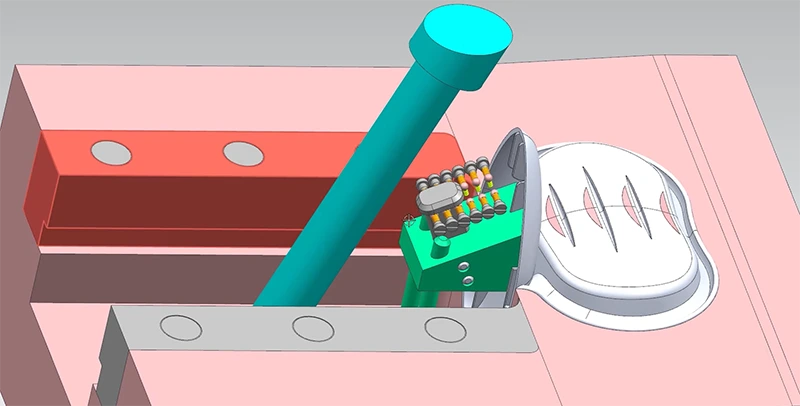
8. Design Housing or Support Structures
Components should be securely housed in a robust and stable support structure. The housing supports the components and further protects them from external damage.
1) Material of the support
It should be strong and durable enough to withstand operational stresses and loads and remain firm in different environments. Aluminum alloys and high-strength steel have good structural integrity and wear resistance.
2) Structural design
The structure should in a way be able to evenly distribute loads imposed by the components. This aids in preventing damage and deformation to the components. It should be rigid and stable enough to reduce movement and flexing during operations.
3) Ease of installation and removal
This is especially important during repairs and maintenance.
4) Component integration
Proper alignment of components inside the housing is important to avoid misalignment and binding during operation. Adequate spacing within the housing will allow free movement of the components to prevent interference and friction during the process.
5) Protection and safety
Incorporate guards or enclosures as a safety precaution from contaminants such as debris, coolant, or dust. This improves the functionality and maintains cleanliness. Access points or removable panels should be necessary, for easier maintenance and inspection purposes.
6) Testing and Validation
Conducting structural analysis of the housing builds confidence in the structure to withstand the expected loads and stress without failure. Fabricate and test a prototype to validate its design and functionality for easier adjustment in case of a problem.
7) Documentation
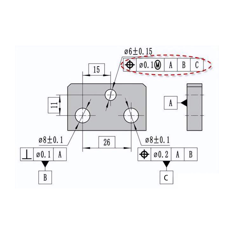
Make a detailed drawing and specifications of the housing featuring, tolerances, dimensions, and assembly instructions. Establish guidelines for inspection and maintenance to assure long-lasting performance.
9. Performing Stress Analysis
Analyzing the design is important to establish the component’s structural integrity and avoid malfunctions during operation. Creating a prototype and using computer simulation to test is essential before full-scale production. Using finite element analysis (FEA) or alternative simulation tools, engineers can analyze stress distribution on the system under various loading conditions. It helps in discovering potential weak points. Design modifications are possible based on the results and improve lifters’ performance and durability.
10. Documentation and Finalization of Mold Lifter Design
Comprehensive documentation and a thorough final review are important for providing additional information for manufacturing and assembly. This involves creating detailed drawings like assembly drawings (orthographic projections), material specifications, assembly instructions, or dimensional tolerances and fits. The final review helps to verify the accuracy and consistency of the documents. To ensure they comply with customer requirements and industry standards.
11. Manufacturing and Implementation of Mold Lifters
This is the final stage of the design process. This phase starts when each part is meticulously manufactured according to design specifications. The fabrication process begins with procuring the right materials to precision machining using techniques like CNC until all components are completed. Quality control and thorough inspection are paramount throughout this process. After successful production, installation, and testing happens with great attention to detail. All components are set up properly and securely fastened. In case of any concerns adjustments occurs. This phase ensures the mold lifter is not only produced but also fully tested and operational.
Wnioski
In conclusion, designing an injection mold lifter requires meticulous attention to detail and careful consideration of every step of the process. By following these guidelines, a designer or engineer is confident of producing a high-quality lifter. Ultimately, it will offer the needed support for the production of various products through injection molding.
