Torsional rigidity is a fundamental engineering parameter. It is the ability of a structural member, under torque, to resist twisting. It is a crucial, valuable characteristic for components under load from torsional loads for applications like shafts, beams, and other mechanical parts used in automobiles, aerospace, civil construction, etc. Knowledge of torsional rigidity is critical to determining the strength and stability of these parts because it directly impacts their torsional strength and durability.
Definition and Significance of Torsional Rigidity in Engineering
Torsional rigidity is denoted by the symbol GJ, where G stands for the shear modulus of the material, and J refers to the polar moment of inertia of the cross-sectional area. It represents the amount of torque required to generate a unit twist per unit length of the structural member.
The torsional rigidity indicates the degree of twisting to structure without damage. Torsional rigidity is vital in engineering as it assists in developing parts that require retaining their geometry and performance under twisting load conditions.
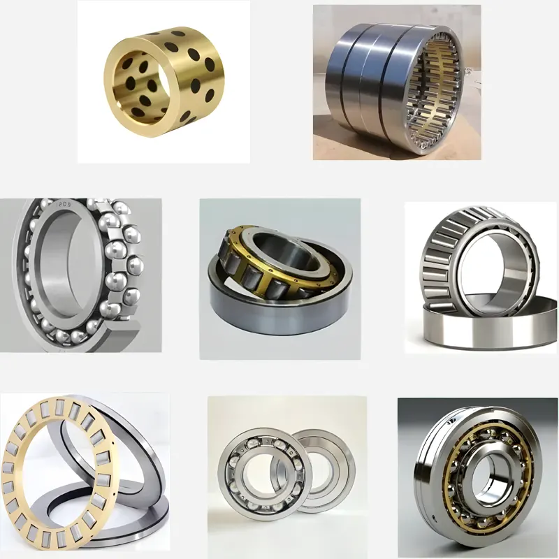
It is precious when applicable where accuracy and strength are critical, such as bearings of mechanical structures, propellers, and load-bearing girders.
Basic Concepts and Physical Interpretation
To understand torsional rigidity, one must think about a cylindrical shaft under torque.
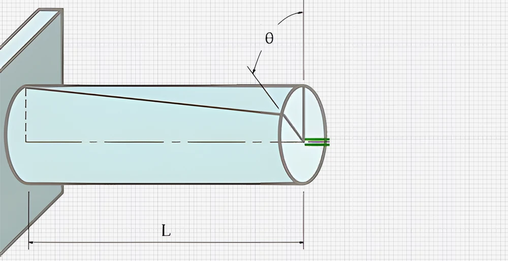
The connection between the applied torque (T), the angle of twist (θ), and the shaft’s length (L) is expressed as:
θ=TL/GJ
From this equation, we realize that the twist angle is directly proportional to the torque as well as the length of the shaft. It is inversely proportional to the torsional rigidity GJ. Torsional rigidity (GJ) represents the resistance of a shaft to twisting under applied torque. The greater the torsional rigidity, the smaller the resulting angle of twist for a given torque. The higher the G and J values, the less the shaft will twist.
Functionally, engineers use torsional rigidity in their applications, estimating how the component will twist under a particular load and determining whether the twist is enough to warrant a failure in structure or hinder the performance of a specific function.
Fundamental Principles of Torsional Rigidity
Torsional rigidity is fundamental in designing and analyzing shafts, gearings, and structures under torsional loads. This involves the ability of a material and its structure to resist the application torque or twisting force, and it depends on the material’s characteristics and the member’s cross-sectional area. Knowledge of these principles is crucial for engineers to design components capable of withstanding torsional loads so they do not deform or fail.
Material Properties Affecting Torsional Rigidity
A component’s torsional rigidity depends on the shear modulus G of the material under consideration. This is a measure of the material’s stiffness in shear stress. The shear modulus of different materials equally varies. Steel possesses a higher shear modulus than aluminum or polymers, which are more flexible types of material. The shear modulus is one of the material constants. It depends on the kind of atomic binding and the material’s lattice.
| Filler Content(wt%) | Matrix Crystallinity(%) | G*(MPa) | σy(MPa) ±0.5 MPa | εr(%) ±(80%) | |
| PE | 0 | 52 | 2.8 | 16 | 1100 |
| PE-Calcite | 9.6 | 48 | 3.2 | 16 | 720 |
| PE-Calcite-SA | 7.7 | 48 | 3.1 | 15 | 720 |
| PE-Aragonite | 10.3 | 51 | 3.45 | 15 | 910 |
| PE-Aragonite-SA | 9.3 | 53 | 2.6 | 16 | 930 |
| PE-C.Fornicata | 8.6 | 49 | 2.8 | 16 | 670 |
| PE-C.Fornicata-SA | 9.5 | 49 | 3 | 15 | 740 |
| PE-C.Gigas | 6.5 | 52 | 2.8 | 16 | 730 |
| PE-C.Gigas-SA | 9.3 | 50 | 3.2 | 15 | 830 |
| PE-P.Maximus | 10.8 | 47 | 3 | 16 | 680 |
| PE-P.Maximus-SA | 9.7 | 50 | 3.2 | 16 | 760 |
Comparison Table of Yield Strength, Ultimate Tensile Strength (UTS), and Young’s Modulus for Different Materials
| Material | Streckgrenze (MPa) | UTS(MPa) | Young’s Modulus(GPa) |
| Aluminium | 35 | 90 | 69 |
| Kupfer | 69 | 200 | 117 |
| Messing | 75 | 300 | 120 |
| Iron | 130 | 262 | 170 |
| Nickel | 138 | 480 | 210 |
| Stahl | 180 | 380 | 200 |
| Titan | 450 | 520 | 110 |
| Molybdenum | 565 | 655 | 330 |
| Zirconium Alloy(Typical Cladding) | 380 | 510 | 99 |
| 08Kh18N10T stainless steel | 216 | 530 | 196 |
| Alloy 304L stainless steel | 241 | 586 | 193 |
| SA-508 Gr.3 Cl.2(low-alloy ferritic steel) | 500 | 700 | 210 |
| 15Kh2NMFA(low-alloy ferritic steel) | 490 | 610 | 220 |
Another material property that influences torsional rigidity is the material uniformity or homogeneity and the extent to which the material is anisotropic or isotropic. The isotropy property enables the torsional rigidity to be constant in all directions in isotropic material.
In anisotropic materials, e.g., composites, the torsional rigidity might differ based on the position of the torque application concerning the material deposition.
Another critical factor that affects torsional rigidity is the selection of material for application. For example, engineers can opt for high stiffness-to-weight ratio composite materials in design areas where torsional rigidity and low weight are critical.
Torsional Rigidity in Different Geometrical Shapes
Torsional rigidity, characterized by the polar moment of inertia, considers the geometry of a component’s cross-section to a reasonable extent. The polar moment of inertia is a geometric concept referring to cross-sectional area distribution concerning the axis of rotation. Different materials have different values of J, hence different torsional rigidities of the cross-sectional shapes.
Circular Cross-Sections:
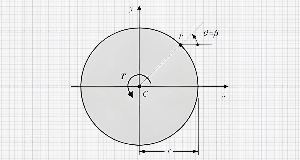
Circular shafts are common in the engineering field. They have a symmetrical distribution of material in its cross-sectional plane around the axis of rotation. The polar moment of inertia for a solid circular shaft is determined by the formula:
J = (πr⁴)/2
where ‘r’ represents the shaft’s radius. Circular cross-sections have a relatively small second moment of area, which enhances their torsional rigidity. Thus, they are used in shafts and rotating parts of machines.
Example 1
Example 1
Suppose a shaft is a solid shaft with radius r = 5 cm and length L = 1 m for the given value shear modulus G = 80 GPa.
- Calculate the polar moment of inertia
- Determine the torsional rigidity
- If a torque T=50 Nm is applied, calculate the angle of twist θ
Lösung
J=(πr4)/2=π(0.05)4)/2=3.07×10-6m4GJ=80×109×3.07×10-6=245.6Nm2θ=TL/GJ=(50×1)/245.6=0.204 radians
Rectangular Cross-Sections:
The other geometric shape of metal bars is rectangular, which is applicable in engineering, particularly structures. With a rectangular bar, the torsional rigidity is much more complicated, and it depends on the aspect ratio of the sides of the cross-section. For thin rectangular sections, where one dimension is much smaller than the other, the polar moment of inertia can be approximated by:
J = (ab³)/3
where this formula is only valid when the thickness is significantly smaller than the width.
Here, a und b are the dimensions of the rectangle measuring length and breadth, respectively. When used as steel members for buildings and structures, rectangular sections are usually less torsionally rigid than circular sections, mainly when their aspect ratio is high, depicting that one side of the rectangle is elongated than the other.
Example 2
Consider a rectangular, thin-walled steel beam with dimensions 20cm by 10cm, a length of 3 meters, and having shear modulus G = 75 x 109 GPa. Determine the torsional rigidity GJ and the angle of twist θ when a torque of T=2000Nm is applied.
Lösung
The polar Moment of Inertia J for a Rectangular Section is given by:
J=(ab3)/3=(0.1×0.23)/3=2.67×10-4
Torsional rigidity GJ=75×109×2.67×10-4=2×10⁷Nm2
The angle of twist is given by:
θ=(2000×3)/(2×107 =1.5×10⁻⁴ radians
Hollow and Complex Cross-Sections:
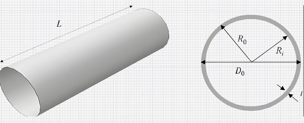
Hollow circular sections like tubes are also helpful in engineering, and non-circular sections such as I-beam and T-section. Cylindrical shells provide good resistance to twisting forces and are relatively light – they can be used in cars as drive shafts or buildings as beams. The polar moment of inertia for a hollow circular section is given by:
J=π(ro4-ri4)/2
Where ro is the outer radius, and ri is the inner radius.
Example 3
Suppose a light, thin-walled hollow circular shaft with outer radius ‘r’ = 5 cm, inner radius ‘b’ = 3 cm, length ‘L’ = 2 m, and the material having shear modulus G = 70 G GPa.
- Calculate the polar moment of inertia J
- Determine the torsional rigidity of GJ
- If a torque T=30 Nm is applied, calculate the angle of twist θ
Lösung
J=π(ro4-ri4)/2=π(0.054-0.034)/2=2.18×10-6m4GJ=70×109×2.18×10-6=152.6Nm2θ=TL/GJ=(30×2)/152.6
Torsional Rigidity in Different Materials
Torsional rigidity depends on the materials. Metals, having a high shear modulus, inherently have high torsional rigidity. For instance, steel possesses a shear modulus of 80 GPa and is helpful in places with significant twisting moments, such as drive shafts and machines. The uniformity of metals prevents variations in the torsional stiffness of the material, allowing it to provide predictable performance in situations that require high accuracy and load-carrying capability.
However, polymers have relatively low shear modulus ranging from 0.5 to 3 GPa, leading to low torsional rigidity. This characteristic renders polymers more vulnerable to twisting under loading.
Nevertheless, their flexibility and elasticity could benefit them when some degree of deformation is allowable. For example, they are helpful in flexible coupling. Comparing the state of torsion in a metal rod and a polymer rod by the application of the same torque, the angle is relatively more significant in the latter. This proves the difference in torsional rigidity of two such materials.
In contrast, composites provide the advantage of tunable characteristics, with torsional stiffness depending on the fiber and matrix materials. While composites may possess a high potential for rigidity, these structures are known to possess anisotropic behavior. This implies that the rigidity is dependent on the direction of the load. Fiber reinforcement alignment is vital and requires precise orientation for optimal performance. Furthermore, torsional rigidity characteristics may also vary in heterogeneous materials such as composites and may not be consistent in all parts of the cross-section.
Table 1: Comparison of Torsional Rigidity in Metals, Polymers, and Composites
| Material Type | Example Material | Shear Modulus (G) in GPa | Polar Moment of Inertia (J)( ×10−6m4 | Torsional Rigidity (GJ) In Nm2 | Relative Density (kg/m³) | Gemeinsame Anwendungen |
| Metall | Steel (AISI 1045) | 80 | 5 | 400 | 7050 | Drive shafts, gears, machine parts |
| Metall | Aluminum (6061-T6) | 26 | 4 | 104 | 2700 | Aircraft components, automotive parts |
| Polymer | Polyethylene (HDPE) | 0.8 | 3 | 2.4 | 950 | Pipes, flexible couplings |
| Polymer | Polycarbonat (PC) | 2.3 | 3.5 | 8.05 | 1200 | Safety helmets, automotive glazing |
| Komposit | CFRP | 100 | 6 | 600 | 1600 | Aerospace components, high-performance sports equipment |
| Komposit | CFRP | 25 | 4.5 | 112.5 | 1850 | Marine components, automotive panels |
Torsional Rigidity in Structural Engineering
Torsional Rigidity in Skyscrapers and Bridges
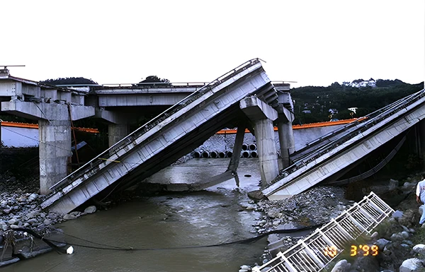
Rotational rigidity stiffness is a crucial element in engineering structures, particularly in the construction of skyscrapers and bridges. One factor in engineering is that the structure must be capable of handling loads without twisting.
For building or bridge construction, it is desirable to have a value of torsional stiffness that can help in withstanding forces that are in a lateral plane, such as wind or earthquake forces.
For example, tall buildings and cantilevered bridges must possess adequate torsional rigidity to resist twisting, which can result in phenomena such as collapse. The manner of formulating the form of the building or the bridge and the pattern of mass and stiffness are customary to minimize the torsional effect.

Importance of Torsional Rigidity in Beams and Columns
Torsional rigidity is also essential in beams and columns. These structural members should have the capacity to resist twisting moments and support the loads. Any member subject to torsional stress, like cantilevers or asymmetrically loaded beams, can in no way be allowed to twist too much.
Similarly, the columns also need to be designed to support any Torsional moments that might arise because of eccentricity in loading or lateral forces. The torsional rigidity of these elements might depend on the cross-sectional shape of these members, materials used, and conditions of support.
For example, compare two bars that have the same cross-sectional area. Circular cross-sectional bars are, as a rule, more resistant to twistiness than rectangular ones.
Real-Life Examples and Design Strategies
Observations from real-life scenarios of torsion failure prove that torsional rigidity requires critical consideration in engineering. For instance, the Tacoma Narrows Bridge, popularly known as ‘Galloping Gertie,’ collapsed in 1940 primarily due to aerodynamic flutter. However, inadequate torsional rigidity indirectly contributed to the failure under specific wind conditions.
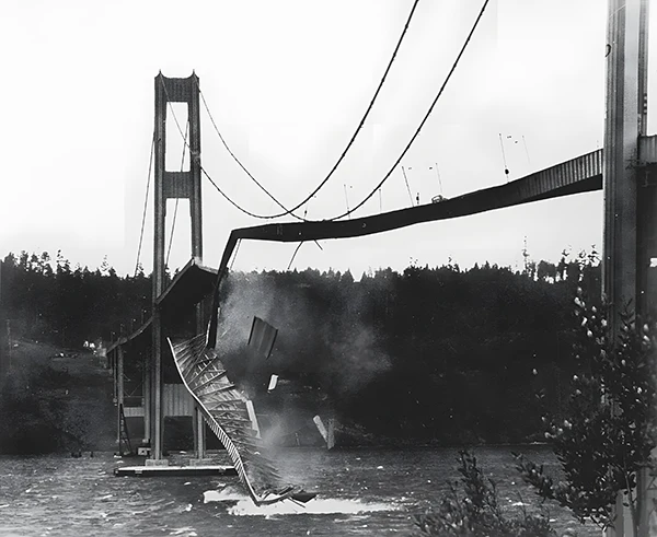
Designers can apply different strategies to reduce torsional issues while designing structures. For instance, they can make cross-sections stiffer. Extending bracing systems that can be of service in the fight against torsion, as well as deploying superior composite materials and technology in structure engineering to enhance torsional performance, is crucial. Engineering practices today also involve computational techniques in analyzing torsional loads and developing structures that can support torsional loads without compromising structural integrity and functionality.
Role of Torsional Rigidity in Mechanical Engineering
Torsional rigidity is useful in mechanical engineering for different areas of machines, such as shafts, gears, and couplings. It ensures that shafts only bend a little under the twisting moment to allow the equipment to function correctly. Therefore, torsional rigidity in shafts is crucial to prevent twisting that could adversely impact mechanical performance or power transmission.
Similarly, gears’ operations rely on torsional stiffness to guarantee correct meshing and the distribution of load during functioning. Adequate levels of torsional stiffness in gears also eliminate slippage while ensuring proper power transmission between gears. In automobiles and aircraft, torsional rigidity increases the efficiency, performance, and safety of the vehicle.
For instance, in automotive engineering, the stationary components of the drivetrain and engine are designed to support high torsional loads during operation.
Schlussfolgerung
Torsional rigidity is an essential factor in the designing and fabrication of parts in structural and mechanical engineering, civil engineering, and much more. It describes the ability of a material or structure to endure twisting force under torque. It specifies the stability of parts for rotational stresses. Torsional rigidity means the stiffness in terms of resistance to twisting in a chosen plane.
Thus, the material properties, the geometry of the structural members, and the specific conditions of utilization help engineers steer to an optimum solution for design problems. Torsional rigidity is beneficial in the structural and mechanical fields to oppose lateral forces for structural stability or functioning of the mechanical equipment.
As such, engineers can design systems that change with operation intent and enhance general functionality by identifying materials and geometric shape problems. In the future, as more engineering technologies are increased, the further optimization and incorporation of torsional rigidity principles are set to boost the appropriate safety and performance of engineered systems.


