Heat sinks have the critical duty of thermal control, keeping electronic devices at an acceptable temperature to avoid high temperatures and subsequent failure. This brings out the importance of balancing principles in the heat sink, such as the thermal conductivity, the surface area, and the type of material applicable. Mastering these concepts can help designers develop efficient heat sinks for heat shedding and extending the life expectancy of components and systems.
Understanding the Basics of Heat Sink
What is a Heat Sink?
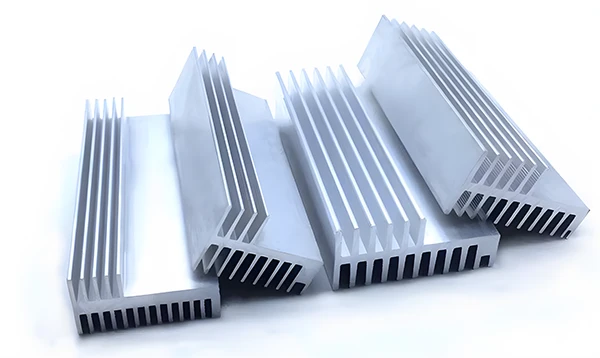
A heat sink is a cooling device that transfers heat to the surrounding system, preventing the hot object from getting much hotter than its surroundings. In simple terms, the central role of a heat sink is to regulate the component’s temperature within permissible maximum limits.
It fulfills this through extended surface area and eases heat dissipation through conduction, convection, and radiation. Heat sinks in electronics are in applications such as CPUs, GPUs, power transistors, or LED lights to guarantee that those components do not overheat and fail.
Essential Components of Heat Sink
A heat sink entails several components that play the role of facilitating the dissipation of heat in electronic components.
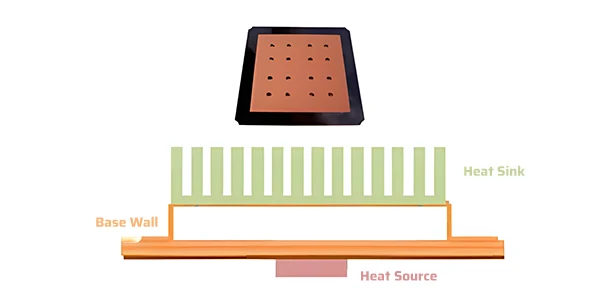
El base sits directly on the heat-producing components, the CPU or power transistor. It is generally metallic, preferably aluminum or copper.
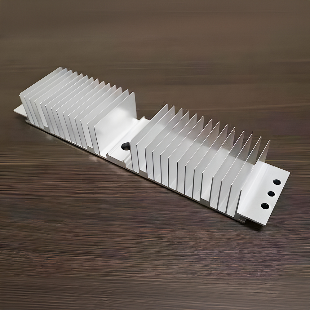
Some fins adhere to the base and increase the output area for heat convection to the surrounding air or fluid.
Some designs include heat pipes to help transfer heat from the base to the finned section.
El mounting mechanism helps fix the heat sinks properly, and a thermal compound compresses the tiny spaces between the heat sink and the component. This is necessary to minimize thermal resistance.
Fans in active heat sinks enhance air circulation over the fins to enhance heat dissipation. Also, some heat sinks may incorporate a guard or casing to control the airflow across the fins more stringently since they are helpful in high-end or cramped applications.
Understanding Thermal Conductivity in Heat Sink Materials
Thermal conductivity (k) is one of the most essential properties in determining how efficiently a material conducts heat. Thermal conductivity is the amount of heat (Q) that passes through a material within a specific time (t) with a temperature gradient (ΔT) over a particular distance (L). Mathematically, it is expressed by the Fourier’s Law of Heat Conduction:
Q=-k×A×ΔT/L
Where: Q= heat transfer rate (W, watts), k= thermal conductivity of the material (W/m·K), A= the area of the cross-section through which heat flows (m²).ΔT= Change in temperature across the material (K) and L = thickness of the material (m).
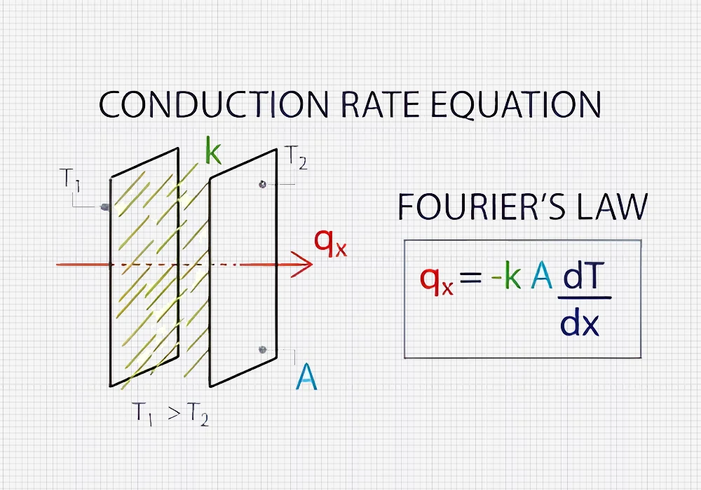
Thermal conductivity is significant in the heat sink application. It enhances heat transfer from the heat source, such as the electronic components, to the heat sink to distribute heat to the surrounding environment. Higher thermal conductivity in materials accelerates heat flow and reduces temperature gradients, increasing cooling efficiency.
Surface Area and its Role in Heat Dissipation
The surface area is one of the most significant parameters directly related to heat dissipation in heat sinks. The greater the amount of the surface area in contact with the cooling medium, most preferably air, the better the cooling since there will be more heat exchange. Newton’s Law of Cooling can describe the heat dissipation rate:
Q=h×A×ΔT
where h represents the convective heat transfer coefficient (W/m²·K).
This equation shows that, when the convective heat transfer coefficient and temperature difference are constant, the rate of heat dissipation is directly proportional to the surface area. This is because a large surface area means many contact points. Thus, more heat transfers from the heat sink to the surrounding air, increasing the cooling effect.
Techniques for Maximizing Surface Area without Increasing Overall Size
In most applications, more so in compact or portable systems, the heat sink size is limited. Methods of achieving a large surface area while containing the structure are helpful.
One technique is the use of fins and pin arrays. This tends to expand the thermal area of the heat sink though this does not much affect the size of the heat sink.
Micro-channel heat sinks have small internal passages and greatly enhance the surface area for thermal dissipation without increasing the outer dimensions. A groove or dimples can increase the micro-scale area to facilitate heat transfer while not changing the dimensions of the heat sink.
Folded fin structures include bending thin metal sheets into fin shapes. They enhance the surface area while keeping the overall area small.
Also, there are porous materials, for example, metal foams with a tremendous internal surface area size for a given volume. However, they have some problems with the airflow and with pressure drop.
Material Selection Criteria for Heat Sink Design
Thermal conductivity is one of the most important parameters when selecting the material for heat sinks. It determines the rate of heat transfer. One of the commonly applicable materials is copper. Copper has a better thermal conductivity of about 390 – 400 W/m·K. This is ideal for high-end applications and is highly conductive. However, copper’s cost and density may pose challenges. Aluminum has a relatively lower thermal conductivity of ~200-250W/m·K. However, it is relatively cost-effective and lighter. This makes aluminum ideal for all-around usage.
New materials such as Graphene have a thermal conductivity of up to 5000 W/m·K. They hold a better future in HSF design with probably the best conventional cooling method. Other composite materials with high thermal performance, such as Metal matrix composites and phase change materials, suggest possible future uses with better thermal efficiency and durability. However, trade-offs are critical and require proper care. Therefore, choosing suitable materials requires considering certain pros and cons about specific application requirements and efficiency, cost, mass, and sturdiness.
| Common Material | Thermal Conductivity (k), (W/m·K) | Cost (USD/kg) | Density (ρ, g/cm³) | Corrosion Resistance |
| Aluminio | 200 – 250 | 2 – 3 | 2.7 | Bien |
| Cobre | 390 – 400 | 6 – 7 | 8.9 | Moderado |
| Acero inoxidable | 16 – 25 | 1 – 3 | 8.0 | Excelente |
| Grafito | 100 – 2000 | 10 – 15 | 1.5 – 2.0 | Excelente |
Heat Transfer Mechanisms in Heat Sink Design
Effective design relies on three primary heat transfer mechanisms: These include conduction, convection, and radiation.
Conduction
In heat sinks, conduction is a process whereby heat from a component transfers through the material to the external environment. Fourier’s Law gives the rate of heat transfer due to conduction:
Qconduction=-k×A×ΔT/L
The mechanism is crucial because it enables heat transfer from the source to the surface of the heat sink, where further dissipation takes place.
Conduction is a significant factor. Therefore, choosing a suitable material is ideal. Thermal conductors like copper or aluminum are helpful because they enable the heat transfer from the hot source to the cold sink surface of the Peltier module.
Copper having good thermal conductivity is widely applicable for high-temperature applications. Aluminium offers low-cost options with reasonable thermal performance.
Besides, the design should also optimize the thermal resistance by maintaining good contact between the heat source and the heat sink. This is possible by employing thermal interface materials that help to improve heat exchange between the two surfaces and overcome thermal impedance.
Particular attention should be paid to the proper distribution of the thermal paths and avoiding gaps or non-uniform contact areas, as these negatively influence heat conduction and thermal management.
Convection
Convection involves the heat exchange between a solid surface and a fluid that flows over the surface, either air or liquid. It involves the movement of heat through the fluid and is described by Newton’s Law of Cooling:
Qconvection=h×A×ΔT
Convection is one of the critical factors in cooling, and it determines the degree of heat dissipation away from the surfaces of the heat sink. Thus, there is a need for maximum surface area to enhance convection.
Using fins or pin arrays means more surface area is available for heat dissipation. Convection efficiency is enhanced from a more prominent head surface since there exists more chance for heat to transfer to the surrounding fluid.
Further, the flow around the heat sink should increase the convective thermal coefficient. This involves applying the use of fans or blowers to increase flow rates, which helps in removing heat at a faster rate.
Radiation
Any object exposed to radiation experiences heat transfer using electromagnetic waves without needing a medium. The Stefan-Boltzmann Law describes it:
QRadiation=ϵ×σ×A×(Tsurface4 – Tambient4)
Where ϵ= the emissivity of the surface (dimensionless), σ = stefan-boltzmann constant (5.67×10⁻⁸ W/m²·K⁴), A= surface area of the heat sink (m²), Tsurface= temperature of the heat sink surface (K), Tambient = ambient temperature (K).
In heat sink design, radiation is one of the most important mechanisms. Applying coatings and finishes that increase emissivity could significantly enhance the radiative heat transfer. Higher emissivity surfaces can radiate thermal radiation more effectively, thus helping in heat dissipation. Moreover, the geometric characteristic of the heat sink also plays a vital role in how effectively radiative heat dissipation occurs. To achieve an efficient heat sink, features expose as much of it as possible to the environment for heat dissipation. In many heat sinks, thermal radiative heat transfer optimization involves using high emissivity coatings combined with geometric designs.
Geometry and Shape Optimization in Heat Sink Design
Surface Area and Heat Dissipation
The efficiency of a heat sink significantly relies on the surface of the device since the heat transfer rate by convection is dependent on the surface area. To calculate the necessary surface area for a given heat dissipation rate, use the following equation for convective heat transfers:
Q=h×A×ΔT
Suppose a heat sink is to dissipate 50 W, with a convective heat transfer coefficient h=50 W/m².K. Suppose also that the temperature difference between the electronic device and environment is ΔT =55K:
A=Q/hΔT=50/(50×55)=0.01819m2 or 182cm2
Conduction through a Heat Sink
To calculate the heat through a heat sink material, use Fourier’s Law of Conduction:
Qconduction=-k×A×ΔT/L
Suppose we choose aluminum as the material then k=205 W/m.K, ΔT=55 K, and thickness L=0.01 m, and cross-sectional area A=0.01 m²A = :
Qconduction=-205×0.01819×55/(0.01)=20.509kW
Optimizing Fin Geometry
To determine the effectiveness of fins in a heat sink, use the following equation to calculate the heat transfer rate from a single fin:
Qfin=(k×Afin×ΔT)/L [1/√((h.L)/k)]
Where Afin = Surface area of a single fin (m²)
Heat Sink Design Process
Formulating the heat sink involves several processes. Each stage demands particular engineering computations to help maximize thermal efficiency.
1. Define Requirements:
To define the heat sink’s performance, three critical factors must include heat dissipation requirement (Q) in watts (W). For instance, if an electronic component dissipates 20 W of heat, Q= 20 W. Next, determine the ambient temperature (Ta), which is the temperature of the surrounding environment. Typically, Ta = 30∘C. Also, specify the maximum junction temperature (Tj) for operating the component. For instance, Tj=85∘C=85∘Last, arrive at the desired temperature rise (ΔT) by subtracting the ambient temperature from the junction temperature.
ΔT=Tj-Ta=85-30=55oC
2. Calculate Required Thermal Resistance(Rth):
Determine the thermal resistance the heat sink must meet for the desired temperature rise.
Rth=ΔT/Q=55/20=2.75 °C/W
3. Select Heat Sink Type and Material:
The type and material of the heat sink selection depends on factors such as thermals, weight, and cost. Some of the most common types are aluminum and copper. For example, aluminum has a (k) thermal conductivity of about 205 W/m·K, which makes it suitable for use due to its effectiveness and cost.
4. Determine Heat Sink Geometry:
Adjust the size and shape of the heat sink to meet the required thermal resistance levels. Selecting from the options on the geometry could include fin type, pin type, or both. For fin type, calculate fin spacing as:
Fin Spacing=Heat Sink Height/Number of fins
5. Perform Thermal Calculations:
When selecting the heat sink design, ensure that thermal resistance calculations have been met. Air convective heat transfer coefficient (h) is usually 10 – 50 W/m²·K. Calculate the effective thermal resistance as:
Rth,total=Rth, heat sink+Rth, interface+Rth,junction
Where Rth, heat sink= thermal resistance of the heat sink, Rth, interface= thermal interface resistance, Rth, junction= thermal resistance from the junction to the interface.
For the heat sink:
Rth, heat sink=1/h.Atotal
Where Atotal=surface area available for heat dissipation.
6. Prototype and Test
Construct a physical heat sink following the design information and evaluate the results. Solder the heat sink to the electronic component and use a thermometer to measure the temperature differential to assess the heat sink’s performance. Finally, depending on the results, some modifications might made to the design to achieve the necessary thermal resistance.
Common Design Mistakes and How to Avoid Them
Thermal management is vital, specifically when designing it for electronic devices. However, several errors are likely to create a negative impact. One common mistake that most people make is needing more space on the surface of the heat sink to allow for proper heat dissipation. One problem in practice is that the designers must perform basic calculations and simulations to determine what surface area is essential for the heat load. This can result in increased temperature regimes and even thermal shock of the components.
Consequently, the interfaces between the heat source and the heat sink can directly increase the thermal resistance and thus lead to low thermal dissipation. Further, any inadequacy in the fins, including fin thickness or spacing, can interrupt the airflow and detract from convective heat transfer, increasing operating temperature. Thus, proper calculations and the use of tools such as Computational Fluid Dynamics (CFD) are helpful to designers in predicting the surface area and fin geometry more correctly. To have the appropriate thermal transfer, one must utilize good-quality TIMs and smooth, flat surfaces for contact.
Conclusión
Heat sink design is crucial in achieving desirable thermal operating limits on the electronic components. An adequate heat sink must incorporate correct thermal conductivity, airspace, and materials as integral parameters. Their proper implementation boosts the component’s durability and system performance.
Conduction, convection, and radiation play critical roles in the heat loss process. Therefore, the principles behind these mechanisms must be fully understood.
Better materials and methods for high thermal conductivity materials and geometries when constructing heat sinks can provide high levels of improvement. The iterative search for new possibilities of materials and designs helps increase thermal product development.
