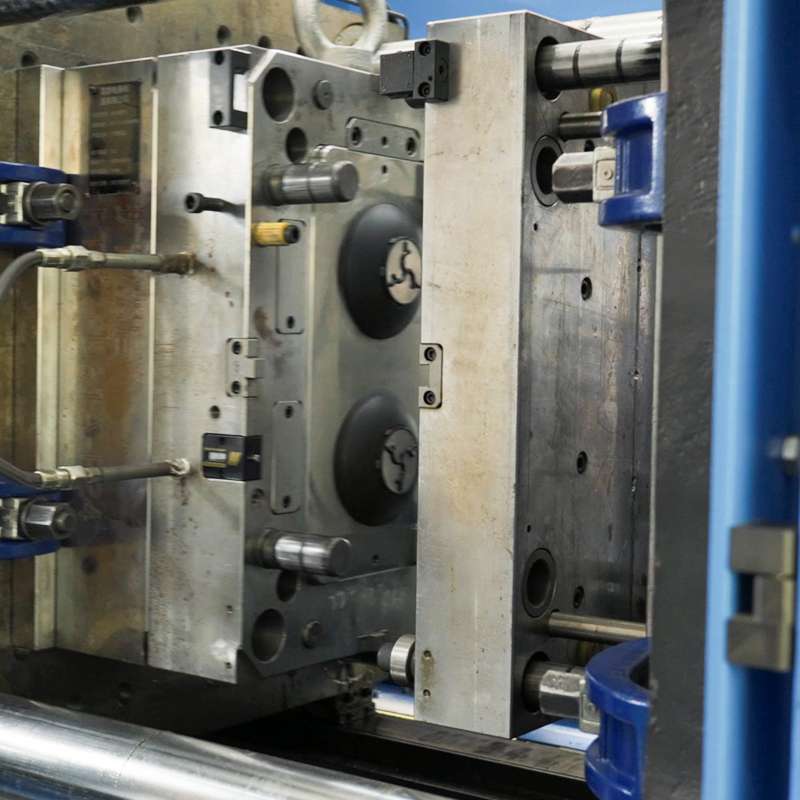
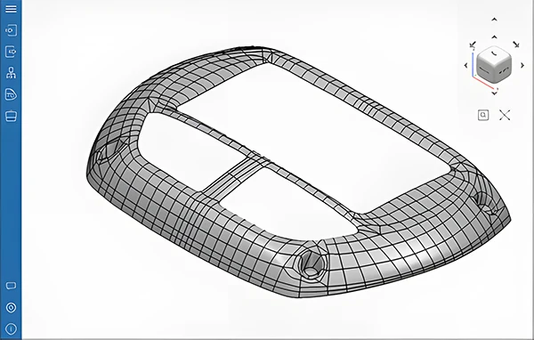
The IGES (pronounced eye-jess) denotes Initial Graphics Exchange Specification and is a well-established file format that facilitates digital data interchange across 3D computer-aided design (CAD). The file is normally saved as IGES or a.IGS. The information in the file is mostly about the model’s surface. However, it may also accommodate data like solid models, circuit information, or wireframes. IGES files are kept in ASCII format and follow the Initial Graphics Exchange Specification.
The IGES file format originated in the mid-1970s, developed as a standardized solution for sharing complex geometric models across different software platforms. This ensured smooth industry and professional collaboration and interoperability.
IGES is a cornerstone in the world of 3D modeling. Designers and engineers can exchange product design data seamlessly in a neutral format, which is extensively used. In applications like manufacturing and prototyping, the IGES format is essentially used to share data since it does not compromise their integrity.
IGES files are especially crucial in sectors that rely heavily on CAE, CAM, and CAD, where accuracy and precision are paramount. The IGES format makes it possible for different systems to “speak the same language,” which makes it easier to interchange data.

History of the IGES Format
Origins of IGES in the late 1970s.
The IGES format was first introduced in the late 1970s when the US government noticed that contractors were spending a lot of time and money trying to get shared data files to function across their different software programs. To solve this critical problem, major industry players like Boeing and the National Bureau of Standards (now NIST) led to the establishment of IGES. The objective was to develop a common file format for sharing 2D and 3D geometric data across systems.
Evolution and adoption across industries.
IGES gained quick traction due to its ability to handle complex designs like; surfaces, solid models, and wireframes. As a result, it evolved into a variable tool for industries like manufacturing and aerospace. As CAD technology advanced and became more complex, IGES got upgraded and modified frequently to accommodate new features and capabilities. Over time, IGES became the de facto standard for 3D data exchange across several applications.
Development of other standards like STEP and STL.
While IGES significantly contributed to the growth of 3D data exchange, other standards also emerged to address certain demands and challenges. One such standard is STEP (STANDARD for the Exchange of Product Model Data) established in the 1980s as a more thorough and adaptable substitute for IGES.STEP incorporates a wider form of product lifecycle data, such as production, design, and maintenance data. Stereolithography, or STL, is another popular format mainly used for Impresión en 3D. A quick and easy method to represent 3D surfaces for manufacturing is through the STL file format. It shows 3D models as a collection of triangular facets.
While IGES remains widely used, these newer formats are becoming more and more popular in sectors that require more accurate and dependable data transfer.
How IGES Files Work
Technical explanation of how IGES stores data.
The IGES format acts as a neutral format for exchanging 2D and 3D data amongst various CAD systems. It encourages seamless communication among software programs. It stores data in a plain text format, which is readable by many applications.
These 2D and 3D designs form encoded geometric curves and surfaces, which is the precise method of processing designs. This implies that produced components will resemble their digital representations quite closely.
IGES permits additional data like comments, text, and dimensions, but its capability to handle such information is limited compared to more modern file formats.
The IGES format is vendor-neutral and can store and open similar data types across multiple platforms. This is regardless of the possibility that they are created by different developers. Unfortunately, it’s challenging to convert an IGES file to another format and back again without sacrificing the quality.
File Structure
IGES file is made of several structures.
The start Section outlines the file and the entry section where actual data is kept. The directory section follows, which provides the file overview consisting of version number, creation date, and list of other sections. The parameter data section stores specific details of the entities. This involves geometric data for 2D (lines, arcs, ellipses, splines, circles) and 3D (curves, surfaces, solids) shapes. Additionally, it offers detailed descriptions of surfaces and curves, such as mathematical equations that define them.
When using an IGES file, the data recipient can inspect and modify the model. The main benefit of using an IGES file is that it guarantees compatibility between various CAD applications. Additionally, an IGES file is used as a backup to secure storage and the transfer medium of 3D models.
To use an IGES file, the user must first open it through their compatible CAD software. Users may access the file through a conversion tool or directly from the application. However, the ability to open or edit an IGES file depends on the capabilities of the specific CAD software being used.
How to Open and Edit IGES Files
Most CAD programs or any other text editor can open an IGES file on both Windows and Mac. Additionally, some web-based file viewers can be used to open and view IGES files online without having to download any software. A few named are; A360 Viewer, FreeCAD, Onshape, and TraceParts. However, you can’t use a web browser to open an IGES file, although Android and iOS have some apps that can assist.
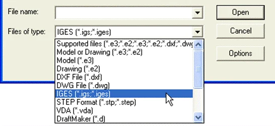
Opening and editing IGES files is a straightforward procedure. Popular tools that can open, edit, and convert IGES files comprise AutoCAD, Solidworks, CATIA, and Fusion360.
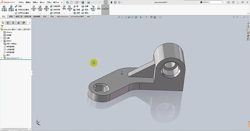
An example of a detailed tutorial on opening an IGES file in Solidworks and Fusion360:
SolidWorks:
- Open SolidWorks.
- Navigate to “File” > “Open.”
- Set the file type filter to “IGES (*.igs).”
- Browse to the IGES file and click “Open.” SolidWorks will automatically recognize and import the data.
Fusion 360:
- Open Fusion 360 and sign in.
- Go to “File” > “Open.”
- Choose “Upload” and drag the IGES file (*.igs or *.iges) into the workspace or browse your files.
- The IGES model is imported, and ready for modification.
Editing and Converting IGES Files.
Once the import of the IGES file is complete, many CAD programs offer the flexibility to modify the model directly. Editing includes modifying geometric data, adding annotations, and making other necessary adjustments.
In certain situations, the user might need to convert the file into another format. For instance, IGES to STL for common 3D printing or from IGES to STEP for a more modern file format.
For example, to export or convert
In Solidworks
- Once the file is ready, select File > Save As,
- choose the target file format (e.g., STEP or STL).
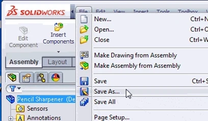
In Fusion360
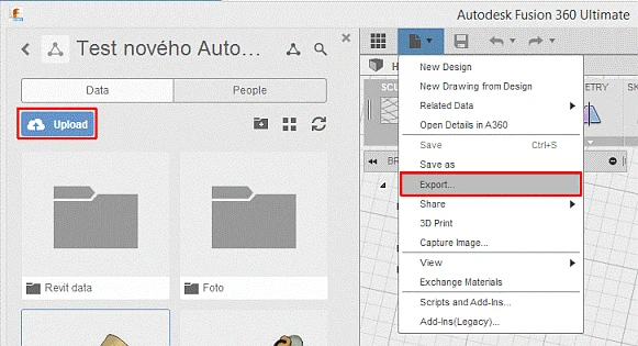
- Once the model is ready, go to the File menu and choose Export.
- En el Export dialog box, select the format you wish to convert the file into. Available formats include:
- **STEP (. step, step) for other CAD programs.
- STL (*.stl) for 3D printing purposes.
- DWG (*.dwg) for 2D drawings.
- DXF (*.dxf) for vector-based drawing exports
IGES vs. Other Formats
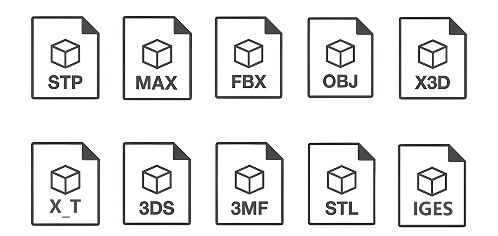
IGES vs STEP
They are both “neutral file formats.” They are compatible with using various 3D packages but have different strengths. STEP is the successor of the IGES format. IGES, an older format, is widely compatible, though it occasionally fails to preserve complex data. STEP is more reliable in data integrity preservation. The reason is that it’s frequently chosen when transferring data between other CAD systems.
Comparison Table
| IGES (Initial Graphics Exchange Specification) | STEP (Standard for the Exchange of Product Model Data) |
| Surface and wireframe modeling, legacy systems | Surface and wireframe modeling, legacy systems |
| Supports 2D & 3D geometry, wireframes, curves, annotations | Supports 2D & 3D geometry, solid models, assemblies, PMI (Product Manufacturing Information) |
| Broad compatibility across older and current CAD systems. | Widely used in modern CAD systems but not as common in legacy platforms. |
| Less precise for solid models, mainly surface-based. | High precision, ideal for solid models and detailed manufacturing data |
| Text-based format with multiple sections | A more structured format that supports metadata and relationships between parts |
| Ninguno | Full support for parametric data (dimensions, tolerances, etc.) |
| No native support for assemblies | Supports assemblies and multi-part structures. |
| Easy to read and understand, but outdated for complex models | Modern, but files are more complex and detailed |
| Often converted to STEP for better support of solid models | Used as a default format for modern CAD data exchange |
IGES vs. STL
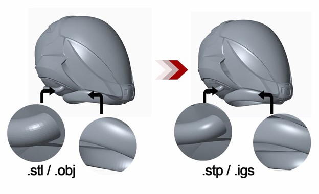
If you own a 3D printer, you’re likely familiar with STL files. STL format is one of the popular formats for storing 3D models. The model’s outline is kept as a set of triangular facets defined by vertices joined by edges. Many CAD and CAM tools accept the STL format for storing 3D models. However, the IGES format theoretically stores files with a higher level of precision. Wider applications can benefit from the IGES format because it holds extra CAD data, such as circuit diagrams.
Comparison Table
| IGES (Initial Graphics Exchange Specification) | STL (Stereolithography) |
| Surface and wireframe modeling, CAD data exchange | Surface geometry for 3D printing and prototyping |
| Supports 2D & 3D geometry, wireframes, curves, annotations | Supports 3D surface geometry (triangular mesh) |
| Broad compatibility across older and modern CAD systems | Supported by most 3D printing and CAD software |
| Text-based format with multiple sections | Simple format using triangulated mesh for surface representation |
| Ideal for Exchanging CAD models, especially surface and wireframe data | Used for 3D printing, prototipado rápido, and surface geometry sharing |
| May convert to STL for 3D printing | Cannot easily be converted to formats like IGES or STEP |
IGES vs OBJ
The OBJ file format established by Wavefront Technologies was meant for animations but has since embraced the 3D community. Similar to STL files, OBJ files describe 3D models by organizing vertices into a network of connected edges. However, OBJ files can additionally handle polygonal faces. They are more compact and effective than IGES files, making them ideal where file size and processing time are essential.
Comparing Table
| IGES (Initial Graphics Exchange Specification) | OBJ (Wavefront OBJ) |
| CAD models, wireframes, and surface models for engineering | 3D models for visual effects, animation, and rendering |
| Supports 2D and 3D geometry, wireframes, surfaces, annotations | 3D geometry (vertices, faces), supports materials and textures |
| Broadly compatible with legacy and modern CAD systems | Widely supported by 3D modeling and rendering software (Blender, Maya, etc.) |
| No support for materials or textures | Supports materials y textures through companion MTL files |
| Often converted to formats like STEP for modern CAD use | Able to be converted to other formats like STL for 3D printing, but lacks engineering details |
| High precision for engineering designs and geometric data | Good for visual representation, less precision for engineering data |
| Typically larger for complex models with annotations | Possible to be smaller or larger depending on texture and detail level |
Benefits and Limitations of IGES Files
Ventajas
- IGES files are stored in ASCII text format making them small and easy to share.
- Interoperability: being the oldest CAD format, it is supported by various CAD applications, simplifying its compatibility across software.
- Legacy support: is frequently used in older systems, enabling data exchange in longstanding projects.
- Industry Standard: IGES has remained popular in many engineering industries like aerospace and automotive since it can handle complex data.
- Detailed Representation: technical documentation like annotation benefits from IGES’s ability to handle complicated geometries
Limitaciones
- Outdated Format: IGES hasn’t been standardized since 1996, meaning the format is not as up-to-date. Newer formats like STEP and Parasolid enhance support for parametric data and solid models.
- It can be challenging to convert IGES files to different file types and back again. These files are based on ASCII data, thus there isn’t much space for conversion. Errors that must be fixed could result from any modifications made to the data during conversion.
- No Solid Model Support: IGES primarily focuses on surface and wireframe geometry. Most CAD applications work better with solid models, which can limit their use in modern applications.
Resumen
IGES files have been essential in the CAD landscape since their inception. Functions as a universal translator, enabling seamless data exchange between various CAD software. While IGES remains a usable option for exchanging design data in legacy systems, more modern formats like STEP offer better capabilities for handling complex designs and are increasingly preferred in most industries. As technology advances, it’s worth considering more modern alternatives that can address the demands of recent designs.


