Geometric Dimensioning and Tolerance (GD &T) are critical in precision engineering, contributing to high-quality designs. They play a role in defining and communicating partitions in the parts in the manufacturing processing systems. GD &T set clear paramours of feature deviations of the parts under manufacturing from the nominal design. It helps mitigate minor inconsistencies in the processing line.
Through GD &T, engineers and technicians can accurately interpret complex geometries and diverse dimensional provisional. This approach helps manufacturers produce parts that fit in a particular tolerance range.
Datum is one of the basic elements that GD &T engineers use to ensure a specific fit in the manufacturing process. It is a critical concept in establishing the coordinate system for other features of parts manufacture.
In this discussion, “part” refers to an engineering specimen, product, or component under design, measurement, or repair. The term “feature” refers to elements of the part or characteristic of a datum. The description of the datum is in respect to the part.
Definition and Importance of Datum in GD&T
In GD &T, a datum is a reference point, line, or plane from which other measurements, locations, and orientations of other features of the engineering project originate. Engineering designers develop new points about the datum, which determines the scope of the new points’ location, modification of the existing measurement, and readjustment of the present points.
For instance, in a 2-D engineering drawing, a datum can be a horizontal line from which all the altitudes and generations of other horizontal lines are made. The intersections of these horizontals and altitudes lead to new points of the parts that manufacturers intend to acquire.
A datum can also be a plane, a flat bottom surface, of the part from which designs measure other features.
An axis can also form a datum for the cylindrical parts in creating holes. Such datum ensures that the part under manufacture aligns with other components for effective joining and coupling. It offers orientation, location, and form control in GD &T. Apart from providing a common starting point for measurements, it ensures proper positioning of features relative to other features. It also enforces the geometric integrity of key features of the part, including concentricity, flatness, and flatness.
Datum is very important in controlling part geometry. First, it provides a consistent reference for measurement irrespective of who performs it and where measurements occur. It ensures order and consistency of the features, minimizing cases of deviations. The second datum ensures that components in engineering assembly fit together as preferred. The absence of data can result in the misalignment of parts, leading to poor performance of the end products. The third datum helps to prevent tolerance stack-up issues resulting from multiple deviations. Engineers anchor tolerances in the datum, controlling the deviation limit of the part feature.
Datum is also critical to quality control. Engineers use it to verify parts to ensure they conform to design specifications. Tools like Coordinate Measuring Machines (CMMs) rely on datum points for accurate and repeatable measurements.
Types of Datum in GD&T: Primary, Secondary, and Tertiary
Datums present themselves in three hierarchical levels: primary, secondary, and tertiary. Reference to this datum should be sequential, with the primary datum being the most preferred and the tertiary datum the last preference.
Primary Datum
This datum is the most preferable level of data where engineers take all other measurements. This datum forms the foundation of the parts’ orientation. There must be enough contact points on the flat surface to effectively constrain one degree of freedom (1 DoF), a translational and rotational movement. The selections of primary data depend on three key characteristics, including stability, functionality, and contact points. The reference for part positioning in the primary datum must be stable and consistent.
For flat surfaces, three contact points establish the primary datum plane. An example of the primary datum is a mechanical part with a flat surface on the bottom. For instance, during the inspection of an engine box, the part sits on a flat surface, which acts as a primary datum.
Secondary Datum
The selection of this reference point follows the primary datum. Engineers and designers select this reference to constrain the part further and remove additional DoF. The secondary datum requires two or more contact points on the part.
In most cases, the point of contact is either the axis or surface interacting with the primary datum to define the part orientation. The secondary datum should orient the part in the second axis or rotational plane and interact with two points on the feature leading to orientation.
The secondary datum should also align with the part under manufacturing concerning the primary datum. An example illustration is the cylindrical part. In this case, the cylindrical surface can be a secondary datum. Once the flat surface becomes the primary datum, selecting the cylindrical surface as the secondary datum can constrain the rotation of the part about a cylindrical axis.
Tertiary Datum
Tertiary datum is applicable when fully constraining the part. It is necessary when completely removing the third DoF. In the tertiary datum, one contact point stabilizes the part on the third axis to ensure the full constraint of the part in 3-D space.
In its functionality, the tertiary datum fully locks the remaining DoF, constraining any movement or rotation. It fulfills full constraint through at least one point contact, possibly a corner.
An illustration of the tertiary datum is a mechanical part with a flat base and cylindrical feature. The flat base forms the primary datum, while the cylindrical feature can create a secondary datum. Adding a small hole can serve as a tertiary datum. This hole locks the final DoF, ensuring precise part orientation during assembly.
Datum Reference Frames: Establishing a Coordinate System
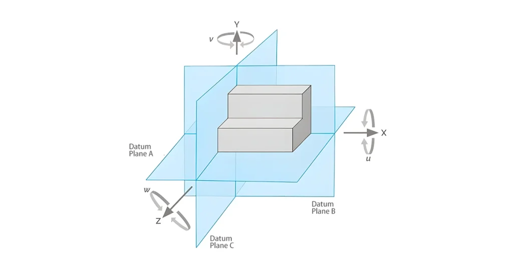
Datum reference frame (DRF) is a vital concept of GD&T. It is critical in controlling part geometry for accurate measurements in the manufacturing assembly. The three sequential data, primary, secondary, and tertiary, are part of the DRF. Different features, including axes, flat surfaces, and holes, are key reference points, lines, and planes leading to the construction of DRF. These features are datum establishing a 3D coordinate system for accurate measurement, orientation, and positioning of the part.
DRF defines 6 DoF, including translations in the X, Y, and Z axes and rotations in each of these axes. DRF fully defines the part in space by constraining movement in these 6 DoF.
Steps in Creating DRF
- Choose a primary datum to provide the main reference for part orientation. This primary datum establishes the first coordinate system by constraining movements along the plane. This step locks the first set of DoFs.
- Establish a secondary datum, which locks the second set of 2 additional DoFs. This step helps define the second axis of the coordinate system.
- Choose the tertiary datum to lock the remaining DoF. This datum ensures full fixing of the datum frame. It defines the last axis or plane, thus completing the 3-axis coordinates system.
Planes of DRF
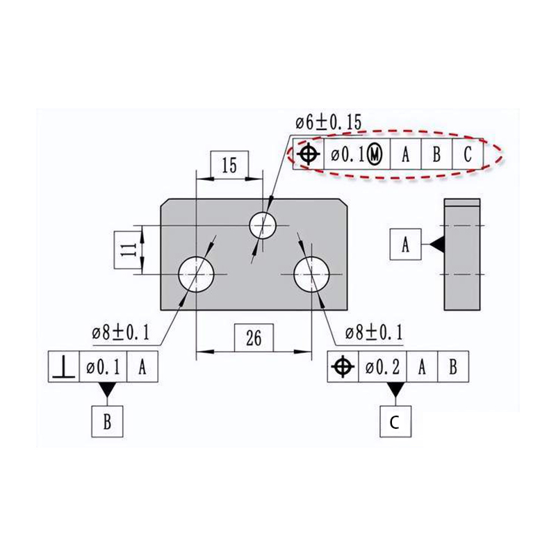
The three DRF datums—primary, secondary, and tertiary—generate three perpendicular planes that lead to the 3D coordinate system. These datums include datum A, datum B, and datum C.
Datum A is the primary reference constraining 3 DoFs. A flat surface or an axis can serve as datum A. For example, for a part with a flat surface, the flat bottom can be datum A. Datum B is perpendicular to datum A. It defines two more DoFs. For example, the side face of a part can be datum B. This datum plane orientation aligns with key features like edges or holes. Datum C is perpendicular to datum A and datum B. It ensures a full definition of the part in 3D space. It can be a smaller feature like an edge.
How Datums Impact Tolerances and Assembly
Datums have a direct influence on the application of tolerances to part features. It consequently dictates how parts fit in the assemblies in the design process. Proper making and defining of the data enhances close control over geometric correlations of the features. This relationship helps with tolerance management, reducing errors and leading to effective assembly performance.
One of the impacts of datums on tolerance is controlling feature location and orientation. Engineers define tolerance relative to datum, ensuring proper positioning of surfaces, holes, and slots to exact places, even with slight variations in manufacturing. For instance, two dimensions from Datum plane A and Datum plane B can define the hole’s location. While tolerance specifies possible deviation range, with datum reference, the hole aligns with other features within the deviation range.
The second impact of datum is improving geometric control. At least one datum dictates the geometric tolerances of GD & T, like concentricity, flatness, and parallelism. Manufacturers can anchor tolerance to datum, controlling the variations in feature geometry without interfering with functionality. For example, manufacturers can control the flatness of the surface relative to datum A. Anchoring the datum with flatness tolerance conditions the deviations to remain within possible allowable limits for effective assembly.
The other impact of datum on tolerance is reducing tolerance stack-up, where numerous small deviations across features accumulate. These multiple deviations lead to larger errors preventing parts from fitting. Manufacturers can reduce these errors by anchoring tolerances to the datum. For instance, an assembly may have multiple holes to align for fasteners. There will be minimal misalignment risks if the holes have a common datum. However, if the datum is missed, minor location errors in the holes can accumulate to prevent proper assembly.
Common Datum Symbols and Notations in GD&T Drawings
Different symbols and notations represent datums in GD&T. The symbols are the universal framework of datum feature identification. Through these notations, manufacturers and inspectors can effectively communicate an understanding of the geometric relationship of parts.
Datum Feature Symbol
It consists of capital letters enclosed in a rectangular box. This symbol connects to the part of the leader.
Datum Target Symbol
This symbol only applies when a specific area, line, or point represents a datum but not the entire feature. It is necessary when locating a datum on a part of a large or irregular surface. This symbol is a circle with a number. A leader line connects it to the exact point on the part.
Datum Reference Frame Notation (DRF)
This notation defines the part’s orientation and constraint in 3D space. DRF involves a sequence of datum letters showing the hierarchy of datums.
Feature Control Frame (FCF)
FCF is a rectangular box with information on geometric tolerances. It has a tolerance symbol and tolerance value. FCF includes a list of data in use in precedence order.
Centerline Symbol or Datum Axis
This symbol applies to cylindrical features or features revolving around an axis. Its long dashed line indicates that the centerline or axis is the datum.
MMC Symbol
This symbol is a datum modifier with the symbol “M” in a circle. It shows that the datum reference applies at maximum material conditions.

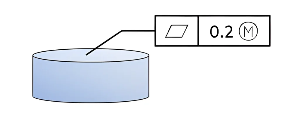
LMC Symbol
This symbol is an “L” enclosed in a circle. It indicates that the datum applies to at least one material condition.

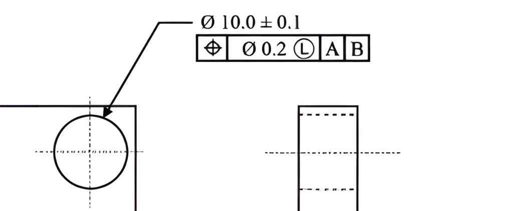
Practical Examples of Datum Application in Manufacturing
Manufacturers widely apply datums in various real-world applications. Tolerance is critical to manufacturing in the aerospace industry, ensuring high safety and performance. DRF helps manufacture large and complex aircraft wings, ensuring alignment and control of critical features.
For example, manufacturers can establish a datum plane along the aircraft wing’s leading edge in the wing assembly. This datum plane can include additional datum points on the wing flaps to define the precise orientation of the wing’s surface. This arrangement ensures effective alignment of all wing parts, including spoilers, flaps, and ailerons.
Manufacturers can apply data in the machining of engine blocks in the automotive industry. While machining engine blocks, technicians or engineers can select the bottom of the block as the primary datum. The centerlines of the cylinders become secondary data. The datums ensure accurate alignment of the boreholes and surfaces.
Conclusión
GD &T play a role in defining and communicating partitions in the parts in the manufacturing processing systems. Datum is a critical concept in establishing the coordinate system for other features of parts manufacture. Datum is one of the essential elements in GD&T, ensuring specific fit and function in the manufacturing process. It plays a critical role in establishing a coordinate system that serves as a reference for other features in part manufacturing.
DRF is critical in controlling part geometry for accurate measurements in the manufacturing assembly. The three DRF datums include datum A, datum B, and datum C. Datums directly influence the application of tolerances to part features.
It consequently dictates how parts fit in the assemblies in the design process. Datums have a direct influence on the application of tolerances to part features. It consequently dictates how parts fit in the assemblies in the design process.
