STL, short for “Stereolithography’, is a popular file format for Impresión en 3D and CAD. It represents a 3D object as a collection of triangles or polygons that define its surface shape. There are backronyms attached to the STL file type which are: Standard Tessellation Language or Standard Triangle Language.
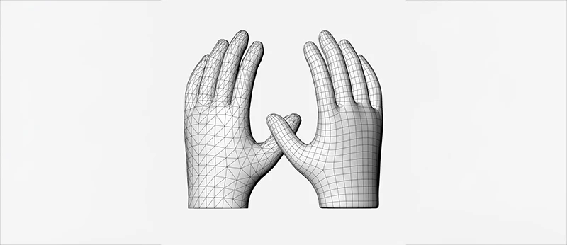
STL simplifies complex shapes into triangular faces, making them easily understandable for 3D printers. The more complicated the design, the more triangles are used ultimately increasing the resolution.
The distinguishing feature of an STL image is its. stl file extension and the absence of color and texture.
History Of The STL File Format
It was established in 1987 by 3D Systems. The STL format swiftly acquired attention as the industry standard for their stereolithographic CAD program. STL was made for 3D printing and has remained relevant due to its simplicity. That’s why it is mostly used in 3D printing and modeling. In 2009, an updated version of the STL file format, STL 2.0, was introduced.
Despite its simplicity, STL’s relevance in the 3D printing and modeling industry has endured.
Benefits Of STL Files In Digital Manufacturing And CAD
Digital manufacturers rely heavily on STL files, which allows designers to design, share, and print prototypes. STL files serve as a bridge between 3D models and physical objects in CAD. This simplicity makes STL indispensable for industries like aerospace and medicine, which often need complex parts.
How STL Files Work
STL files primarily encode the surface geometry of a 3D object, using a process known as “Tessellation.
Tessellation is a technique that simplifies intricate surfaces into simpler, flat polygons. In STL files, these polygons are triangle-shaped. In 1987, Chuck Hull, the inventor of stereolithography, needed a way to send 3D CAD models to his 3D printer. Albert Consulting Group solved this problem by using tessellations of the 3D model’s surface to encode the information.
i) Surface Approximation
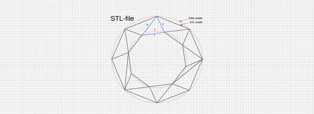
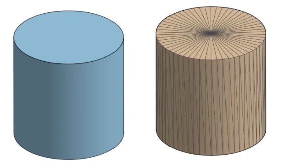
In tessellation, even curved surfaces, like cylinders and spheres are shown by a series of mesh triangles. The smoother the curved surface approximation, the more triangles are needed. However, this also expands the file size and computational complexity resulting in trade-offs between performance and resolution.
ii) Triangles in 3D Space
A triangle has three vertices with each vertex having an x, y, and z coordinate in 3D space. The vertices form the corners of the triangle which joins from one edge to another edge and create the overall surface of the object.
iii) Mesh creation
The STL file structure consists of triangles that form a triangular mesh representing the digital surface map of the object. They are tiny enough to allow an accurate approximation of the original shape yet simple for 3D printers or software to process.
iv) Resolution control
The model resolution is shown by the number of triangles used in tessellation. A higher triangle counts result in a more accurate and detailed model but increases the file size and process demands. On the contrary, a few triangles simplify the model but can make curves look blocky or faceted.
v) STL Representation
In STL files, triangles are useful because they are easier to calculate and work with for 3D printing. Each triangle has an associated normal vector that shows which direction the surface is facing. This assists the 3D printers in understanding how to build the object layer by layer.
Binary vs ASCII STL File Types
STL file comes in two main formats, ASCII encoding and binary encoding.
ASCII STL Files
ASCII STL files are human-readable and provide a plain text description of the orientation and position of each triangle. While they are easier to debug and read, they are larger than binary counterparts.
For instance, a larger file size can become impractical in the case of complex models. A simple 3D model might have 1MB in binary format but when converted into ASCII goes up to 5-10 MB making it hard to transfer files and process. If you are working with a 3D printer or CAD software, it should read and interpret each line. Due to its size, it takes a longer time to load especially complex models delaying the steps.
ASCII STL files start with the keyword “solid” and contain a series of “facet” definitions. Every facet comprises three vertices and a normal vector.
Binary STL Files
Binary STL files are the most preferred choice in various applications because they are compact and efficient. They speed up the processing and reduce the file size of similar information. Handling large-scale projects like complex prototypes or industrial types, companies work with hundreds of files a day. Small files of binary STL reflect fast downloads and uploads reducing bandwidth consumption. Additionally, some operations like rendering and slicing for 3D printing result in quicker processing time.
Binary files are easily manageable by modern 3D software. Editing and error-checking tools like MeshLab, and Netfab can handle these files effortlessly.
Binary STL files begin with an 80-byte header.4-byte unsigned integers representing the number of triangles in the file follow. Each triangle has 12 bytes for the normal and 36 bytes for the vertices (3 vertices)

Creating and Exporting STL Files
Some popular CAD programs allow users to create and export STL files. The most famous ones are:
Solidworks: most used by engineers and professionals in 3D modeling. Provide advanced capabilities like built-in simulations and analysis to test designs before printing. Provides comprehensive STL export options like control over format (ASCII or Binary) and resolution.
Tinkercad: Has drag-and-drop interfaces for easier creation of 3D models. Suitable for beginners and educators who have no prior experience in design. Offer direct export to STL format.
Fusion 360: a popular tool for 3D CAD, CAM, and CAE, is useful in product design and engineering. Provides strong modeling features such as sculpting and parametric design.
Beyond these options, several other CAD tools, including FreeCAD, SketchUp, and Blender, are also capable of exporting STL files.
Creation and Exporting of an STL File
- Open Solidworks or Tinkercad, depending on your CAD application of choice.
- Create the Model or Design with tools from the software.
- Save and export the design- an autosave feature can easily save an STL file created by the software and export it to the computer. However, before exporting check on the model uniformity, holes in parts, and dimensions. Check for resolution, in case of low resolution, the triangles will appear on the model surface after printing. Adjust the tolerance level to be high so that the STL files can be printed seamlessly.
Parameters like the angle and the height of the chord give the distance between the 3D print and the CAD surface. Ideally, the chord height is 1/20th the size of the print surface. Chord length below 1 micron but not too low and angular tolerance 150.
- Choose a slicer program- Cura is the most widely used, open-source slicer from Ultimaker since it’s easier and flexible to use.
- Load the file, and convert it into a G-code (printer language) file using your preferred slicing software.
STL file Special Rule
1. Orientation Rule
This rule defines how the direction of each triangle (facet) is influenced by its nominal vector. This vector shows the direction in which the triangle is facing and assists in determining the inside and outside of the object. The normal vector points away from the surface showing “outside” showing the exterior to the 3D printer. The wrong orientation of the normal alters the interpretation of the features resulting in printing errors.
The vertices follow the right-hand rule, where the thumb points to the direction of normal and the fingers direction of the vertices. This follows the counterclockwise order.
2. Vertex Rule
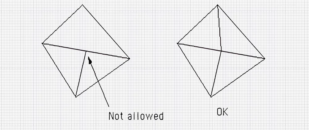
This rule states that every triangle should share two vertices with the triangles. Adjacent to it. This ensures the triangles are accurately positioned and fundamental for bot rendering and smooth operation in 3D printing.
3. The All Positive Octant Rule
According to this rule, all the coordinates of the vertices of the triangles should all be positive. This restricts the whole 3D model or the first octant of the 3D coordinate system. to the area where all coordinates are positive. This simplifies the design and saves on space. This approach simplifies modeling in specific contexts but is not a requirement for all STL files.
4. The Triangle Sorting Rule
Based on the triangle sorting rule, the arrangement of triangles is in ascending order of their z-coordinates. This format streamlines the slicing process for 3D models, resulting in faster and more effective preparation for 3D printing.
STL File Optimization for 3D Printing
STL file format partially recreates a CAD model’s surface by producing a mesh suitable for 3D printing. However, optimization is essential to ensure optimal results. The resolution of the STL file significantly affects the quality of the print. More triangles mean higher resolution and smooth surfaces but increased file sizes. Reducing polygon count by merging vertices or reducing unnecessary polygons lightens the load. The slicing software finds it easier to process and experiences few errors. Finally, a watertight model without gaps or manifolds has to be certain for a smooth process. Sticking a balance between quality and size is key to optimizing STL files.
Alternatives to STL Files
While STL files are a common option for 3D printing, few alternatives offer better features and functionality.
STL vs OBJ
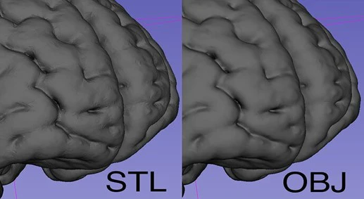
STL files are widely used in 3D printing. They use the triangular meshes principle to encode geometry.OBJ on the other hand is mostly used for 3D scanning. It combines different polygons into a single file to represent the surface.
The table illustrates the comparisons.
| STL | OBJ |
| Simple, triangular mesh | Polygon-based, with support for quads |
| No color or texture support | Supports color, texture mapping, and UV coordinates |
| Typically smaller, but can grow with resolution | Larger due to additional data (textures, colors) |
| Limited to surface geometry (no detail in materials or appearance) | Handles complex geometries, materials, and visual details |
| Best for 3D printing and basic CAD designs | Ideal for detailed models in gaming, film, and visual projects |
| Simple, easy to process | More complex with material libraries |
STL vs STEP
STL files in this case store only surface geometry through triangular meshes, resulting in lightweight and easy to process. STEP files are much more comprehensive. They retain design intent and can save the models as single entities, leading to higher accuracy and smoother curves
A comparison table is as follows:
| STL | STEP |
| Surface-based triangular mesh | Boundary representation (B-rep) and solid modeling |
| No color or texture support | Supports color, material properties, and textures |
| Typically smaller, dependent on mesh resolution | Larger due to more detailed geometric information |
| Simplified surface geometry (no internal structure) | Contains full design data, including complex assemblies and geometry |
| Primarily for 3D printing and simple CAD models | Ideal for engineering, manufacturing, and CAD interoperability |
| Simple, easy to process | More complex, stores both geometry and metadata (design intent, dimensions) |
| Approximate, based on surface triangles | High precision, exact geometry for manufacturing and engineering applications |
| Limited, often requires conversion for CAD software | Highly interoperable across different CAD systems |
STL vs 3MF
3D printing prefers STL files because of their simplicity and compatibility. The 3MF (3D Manufacturing format) file is XML-based and more advanced because it contains all the information required to print an object.
A comparison table is represented below;
| STL | 3MF |
| Triangular mesh-based, surface geometry | The XML-based format supports both mesh and full model details. |
| No color or texture support Completely | supports color, textures, and materials. |
| Typically smaller, dependent on mesh resolution | More efficient compression, smaller file sizes compared to STL with the same level of detail |
| Simplified surface geometry | Handles complex geometries, multi-material models, and more detailed properties |
| Primarily for 3D printing and basic CAD designs | Good for modern 3D printing, especially when multi-material and color are useful |
| Simple and lightweight, easy to process | Structured with metadata (materials, colors, print settings) |
| Approximate, based on triangular facets | Higher precision supports richer design details and metadata for accurate printing. |
| Applicable in 3D printing software. | Usable by modern 3D printers and software due to advanced features. |
STL vs G-code
STL file is for 3D printing. 3D slicer software helps it to communicate with the printer for printing. Comparatively, the G-code file format is a set of instructions guiding the printer process. Common in cutting machines like mills and lathes.
A comparison between the two formats is shown below.
| STL | G-code |
| 3D model data, triangular mesh | Machine instructions, toolpath commands for 3D printers |
| Represents the shape and geometry of a 3D model | Provides precise instructions for a 3D printer to execute |
| No color or texture support | Can include instructions for multi-material printing (if the printer supports it) |
| Can include instructions for multi-material printing (if the printer supports it) | Large depending on print complexity and the number of layers |
| Simplified surface geometry | Contains detailed machine-specific commands (e.g., nozzle movement, temperature settings) |
| Used to represent 3D models for design and visualization | Used to control the printing process, specifying how to create the model physically. |
| Simple mesh-based data | Line-by-line instructions for each movement, temperature, speed, and extrusion |
| Must be converted into G-code via slicing software | Directly readable by 3D printers as manufacturing instructions |
| Approximate, surface-based triangles | Exact, down to specific machine movements and printing parameters |
Conclusión
STL file format has been like the digital blueprints of the 3D printing world. Despite its simplicity and swift translation of digital models into a printable format, it does have its limitations. Regardless of the newer formats’ advanced features, STL remains a go-to option for many designers. Nevertheless, it’s always important to choose the file format according to the intent of the 3D file.
