If you’ve worked with engineering drawings, you’ve probably come across GD&T.
But what does it mean?
As a system of symbols that defines the geometric features of parts, GD&T (Geometric Dimensioning and Tolerancing) allows accurate production of parts with slight dimensional variations. This is a great way for engineers and manufacturers to specify a part’s making, inspection, and assembly to meet its functional requirements.
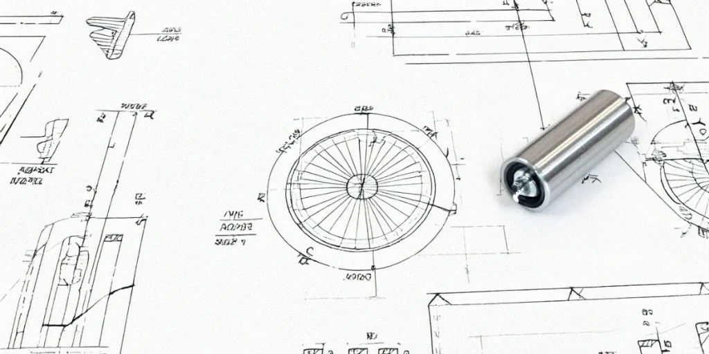
Unlike conventional tolerancing, which relies upon basic coordinate dimensions, GD&T is a functional description of a part’s geometry. It enables the designer to detail precisely how a part should fit together without necessarily detailing every dimension, thus minimizing cost while maximizing quality.
GD&T is critical for attaining the interchangeability of parts and functionality as intended, even when slight variations occur in manufacturing. The automotive, aerospace, and consumer electronics industries greatly depend on this ability to make their products precisely and dependably.
Now let’s take a deeper look into GD&T and how you can implement this system into design practices for increased efficiency.
Key Takeaways
- GD&T is a system of symbols that defines the rules for communicating design intent, offering guidelines through part manufacturing and assembly.
- It standardizes communication, thereby reducing manufacturing costs and ensuring the functionality of manufactured parts with improved quality.
- The GD&T system focuses on size, location, orientation, and form (SLOF) to define parts’ geometric features.
- GD&T uses symbols and feature control frames to define tolerance zones and ensure precise part specifications.
- It also reduces misinterpretation, scrap, and rework in production while improving inspection and functional accuracy.
History and Evolution of GD&T
Most people date the origins of GD&T back to World War II when a Scottish engineer named Stanley Parker introduced an efficient system for tolerancing parts.
He recognized that traditional methods often led to unnecessary part rejections due to strict, non-functional tolerances. Parker’s work pioneered the laying down of functional tolerances, which are not purely dimensional, forming the basis for GD&T.
The US military then adopted these principles in 1949 with the issuance of MIL-STD-8, thus giving birth to the very first standard on GD&T.
Through development over time, the American Society of Mechanical Engineers developed its standard, which became known as ASME Y14.5 and is used as the guiding reference in GD&T. ASME Y14.5-2018, the latest revision, reflects modern manufacturing techniques and continues to guide industries worldwide.
The Benefits of GD&T
GD&T offers several advantages over traditional dimensioning and tolerancing methods, including:
1. Improved Communication
One of the significant benefits of GD&T is that it communicates the design intent clearly and concisely. Because the focus is not on size but instead on the part’s functionality, GD&T allows for the most efficient and accurate manufacturing method.
For this, standardized symbols and feature control frames used with GD&T minimize the chance of misinterpretation, which can occur during traditional dimensioning methods.
For example, specifying True Position in GD&T ensures everyone knows where a hole should be located and how much variation is allowed. This clarity leads to fewer production errors, better quality control, and, ultimately, a more reliable product.
2. Cost Efficiency
GD&T allows for looser tolerances on non-critical features, significantly reducing production costs. So, rather than having tight tolerances on every dimension to increase manufacture time and costs, engineers can apply looser tolerances to many areas of the part.
This ideally helps focus the attention on the critical dimensions that affect the part’s functionality, improving efficiency without sacrificing quality.
Consider the example of a mirror. Using traditional dimensioning, engineers might apply a very tight tolerance to the thickness of the mirror to prevent warping.
This tight tolerance does not guarantee that the surface is perfectly flat. In GD&T, an engineer could specify a flatness control and relax the thickness tolerance, thus making the part easier and cheaper to manufacture
3. Functional and Reliable Parts
GD&T ensures that parts function correctly in their final assemblies, even if individual dimensions deviate within acceptable limits.
By specifying the size, location, orientationy form of critical features, engineers can ensure that a part will meet its functional requirements, regardless of minor variations in less important areas.
For instance, the environment is very extreme in aerospace parts such as turbine blades and requires good fitting. Here, Geometric Dimensioning and Tolerancing ensure this kind of blade keeps its correct orientation and location relative to other components for reliable function under stress.
4. Reduced Waste and Rework
When the design intent is ambiguous, manufacturers occasionally create parts that do not fulfill functional requirements. These parts are then either scrapped or have to be reworked at great expense.
GD&T reduces this risk by clearly defining the acceptable tolerance zones for each feature, reducing the possibility of producing defective parts. This, in turn, leads to higher efficiency and less wasted material.
Core Concepts of GD&T
To understand how GD&T works, one first needs to understand its basic principles. Those are usually referred to by the acronym SLOF, meaning Size, Location, Orientation, and Form.
These four elements are controlled with specific GD&T symbols and a feature control frame defining acceptable tolerances.
Let’s explore each below.
1. Size
In this context, size refers to the physical dimensions of a feature, which could be the diameter of a hole or the length of a cylinder. This is typically controlled using traditional ± tolerances, but in GD&T, other geometric controls often influence the size.
2. Location
The location of a feature is described as where it is in space relative to the other features of the part. The most common symbol used in GD&T that controls location is True Position. This allows features to be properly placed in relation to others, such as drilling a hole in the correct place.
3. Orientation
Orientation refers to how a part or feature is angled in space relative to another feature. Common orientation controls include Parallelism, Perpendicularityy Angularity, which ensure that features are aligned as required. For example, GD&T may ensure that two surfaces are perpendicular to each other to prevent issues during assembly.
4. Form
Form controls how the shape of a feature is defined, often refining its size. Symbols like Planitud, Circularity, Cylindricityy Straightness specify how close a part must be to a perfect form. These tolerances ensure that the part meets its functional needs without unnecessarily tightening other dimensions.

Feature Control Frames in GD&T
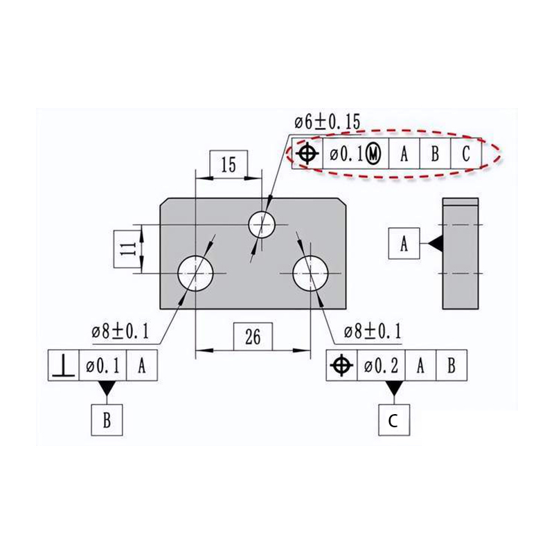
A feature control frame conveys the tolerance requirements for a part’s features. The frame includes the symbol for the geometric characteristic being controlled (such as flatness or position), the tolerance value, any material condition modifiers (such as Maximum Material Condition), and any relevant datum references.
For example, a feature control frame might specify that a hole must be within a cylindrical tolerance zone of 0.1mm, referencing two datums for alignment. The frame ensures the hole is accurately placed and aligned within the required limits.
GD&T Symbols and Their Importance
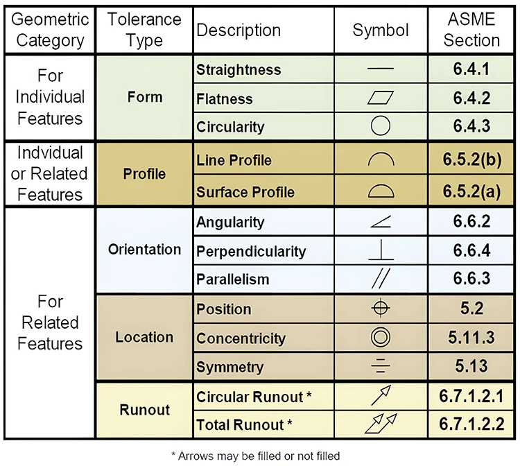
Applying GD&T involves the usage of a range of symbols. Each symbol represents a different geometric characteristic and specifies how a feature must be controlled. Some of the most commonly used symbols in GD&T include:
- Flatness: Ensures a surface lies within two parallel planes.
- True Position: Defines the permissible variation in the location of a feature relative to its ideal position.
- Cylindricity: Ensures a cylindrical part remains within a perfect cylinder.
- Parallelism: Controls how parallel one feature is to another.
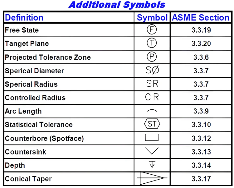
These symbols are used with datum reference frames and tolerance values to ensure that parts are manufactured accurately.
Datum Reference Frames
A datum reference frame is the “skeleton” of a part’s geometry. It establishes a 3D coordinate system to define the tolerances of various features. A datum reference frame typically includes three planes or axes that constrain the part in six degrees of freedom—three translations and three rotations.
A datum is a theoretical, perfect feature (like a plane or axis) used as a reference point for all other measurements. The physical counterparts of datums are called datum features, such as a flat surface or a hole. These features help establish the reference system that ensures every part meets the functional requirements.
Real-World Application of GD&T
When considering real-world usage, GD&T is necessary in industries that require accuracy in tolerances and functional precision. It is generally applied to Computer Numerical Control machining because GD&T can ensure that one specific part will be machined as specified without any uncertainty.
Take the design of a mirror again, for instance. You might specify tight tolerances on the mirror’s thickness using coordinate dimensioning to avoid warping. However, this approach could still result in a wavy surface, even if the part meets the thickness requirement.
GD&T solves this problem by focusing on flatness, specifying that the mirror’s surface must remain within two parallel planes, ensuring a flat, functional mirror without unnecessary tight thickness tolerances.
Another example is the automotive industry, where GD&T ensures parts like engine components fit together precisely. By focusing on position tolerances, engineers can ensure holes and other features align perfectly during assembly, minimizing the chance of failure due to misalignment.
Understanding Material Condition Modifiers
GD&T uses material condition modifiers to add flexibility to the tolerance requirements of a feature. The two most common modifiers include:
- Maximum Material Condition: The condition that exists when a feature contains the maximum amount of material. Now, the MMC of a hole would be its least size or smallest diameter. Meanwhile, the MMC of a pin would be its largest permissible diameter.
- Least Material Condition (LMC): It is a condition of a feature that contains the least amount of material. For the hole, this is the largest acceptable diameter. And for the pin, it is the smallest acceptable diameter.
These modifiers help engineers loosen tolerances without sacrificing functionality, leading to easier production and cost savings.
Tolerance Zones in GD&T
The fundamental core concept of GD&T is the tolerance zone, which designates the limit over which a feature is acceptable. This can be a cylindrical zone for a hole’s position or two parallel planes for flatness.
For example, in the location of a hole with GD&T, the axis of that hole should remain within the space of a cylindrical-shaped tolerance zone to allow minor variations but maintain the correct functioning of the part.
This will enable the manufacturer to place the tolerances where they are truly needed, preventing undue tightness elsewhere.
Why GD&T Matters in Modern Manufacturing?
GD&T is a powerful tool for the modern manufacturer. It facilitates great communication between design and manufacturing teams. Additionally, it ensures parts meet the necessary functional requirements without being over-toleranced. These factors combine to create significant cost savings once parts enter mass production.
The capability to define functional tolerances also allows the designer to create more easily and economically produced, inspected, and assembled parts. With automation and precision, parts can meet strict standards for quality and reliability, especially in the aerospace, medical devices, and automotive industries.
Conclusión
All in all, GD&T is a powerful means of ensuring your design intent is well-communicated and accurate. It helps focus on the functional aspect of parts while defining appropriate tolerances to reduce ambiguities, increase quality, and lower cost.
By mastering GD&T with experts at Primer molde, you can design and manufacture parts that meet the most demanding requirements.
