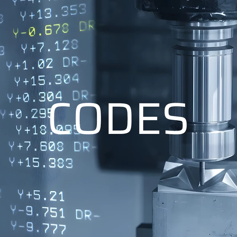
CNC has taken manufacturing to the next level by giving manufacturers the means to achieve high accuracy, speed, and flexibility in making complex parts. G codes and M codes are the two codes at the heart of every CNC program that direct the many operations a given machine can perform. Therefore, it’s crucial for machinists and CNC programmers to differentiate between G code y M code for proper machine operation.
In this article, we will discuss some of the most common G and M codes, how they work in a typical CNC program, and why they are crucial to manufacturing.
G Code in CNC Programming
The G code is mainly the Geometric Code. It is the most common form of programming for CNCs. It tells the machine how it should move-for instance, in a straight line, in a circular motion, or at a feed rate.
Essentially, G codes tell the CNC machine where to put the tool and how the tool should relate to the workpiece based on movement.
Each G code has some action or movement in a CNC machine, and a set of these will be executed in a sequence order to accomplish some task. Although G code programming was initially developed for NC machines, its principles remain basic in modern CNC machining.
Common G Codes and Their Functions
Let’s break down some of the most essential G codes in CNC machining:
1. G00: Rapid Positioning
The G00 command instructs the machine to rapidly move the tool to a specified coordinate without engaging in cutting. It’s typically used to move the tool to a starting position before machining begins or to prepare for a tool change. This is one of the fastest movements the machine can make.
2. G01: Linear Interpolation
The G01 command controls the cutting tool’s movement along a straight line at a specified feed rate. This is often used for precise cutting operations, where the feed rate is slower than with rapid positioning, allowing for greater accuracy.
3. G02: Circular Interpolation Clockwise
The G02 code commands the tool to move in a clockwise direction. This is typically used when the part requires circular cuts or rounded edges.
4. G03: Circular Interpolation Counterclockwise
Like G02, the G03 command moves the tool in a counterclockwise circular path. Collectively, machinists can use G02 and G03 to create complex curved shapes and profiles.
5. G04: Dwell
The G04 command tells the machine to pause or dwell for a specified time. This is useful when the cutting tool needs to hold its position, such as when ensuring the spindle reaches a stable speed or when waiting for the coolant to take effect.
6. G17, G18, and G19: Plane Selection
These codes select the geometric plane in which the machine will operate:
- G17: Selects the XY plane.
- G18: Selects the XZ plane.
- G19: Selects the YZ plane. This is critical in multi-axis machining to ensure the tool moves within the correct spatial parameters.
7. G43: Tool Length Compensation
The G43 code compensates for the tool’s length, allowing the machine to account for different tool sizes during operation. Without this, tools of varying lengths could cause inaccuracies in machining.
List of G Code
| G code | Group | Meaning |
| G00 | 01* | Rapid motion |
| G01 | 01 | Linear interpolation motion |
| G02 | 01 | CW interpolation motion |
| G03 | 01 | CCW interpolation motion |
| G04 | 00 | Dwell |
| G09 | 00 | Exact stop |
| G10 | 00 | Programmable data input |
| G11 | 00 | Programmable data input cancel |
| G15 | 17* | Polar coordinate cancel |
| G16 | 17 | Polar coordinate |
| G17 | 02* | XY plane selection |
| G18 | 02 | ZX plane selection |
| G19 | 02 | YZ plane selection |
| G20 | 06* | Select inches |
| G21 | 06 | Select metric |
| G28 | 00 | Return to reference point |
| G29 | 00 | Return from reference point |
| G30 | 00 | Return to 2nd ,3rd,4th reference point |
| G31 | 00 | Feed until skip |
| G33 | 01 | Threading |
| G40 | 07* | Cutter compensation cancel |
| G41 | 07 | Cutter compensation left |
| G42 | 07 | Cutter compensation right |
| G43 | 08 | Tool length compensation + |
| G44 | 08 | Tool length compensation – |
| G49 | 08* | G43/G44 cancel |
| G50 | 11* | G51 cancel |
| G51 | 11 | Scaling |
| G52 | 00 | Set local coordinate system |
| G53 | 00 | Non-modal machine coordinate selection |
| G54 | 14* | Select work coordinate system 1 |
| G55 | 14 | Select work coordinate system 2 |
| G56 | 14 | Select work coordinate system 3 |
| G57 | 14 | Select work coordinate system 4 |
| G58 | 14 | Select work coordinate system 5 |
| G59 | 14 | Select work coordinate system 6 |
| G60 | 00 | Unidirectional positioning |
| G61 | 15 | Exact stop modal |
| G64 | 15* | G61 cancel |
| G65 | 00 | Macro call |
| G68 | 16 | Rotation |
| G69 | 16* | G68 cancel |
| G73 | 09 | Highspeed peck drilling cycle |
| G74 | 09 | Left-handed tapping cycle |
| G76 | 09 | Fine boring canned cycle |
| G80 | 09* | Canned cycle cancel |
| G81 | 09 | Drilling cycle |
| G82 | 09 | Spot drilling cycle |
| G83 | 09 | Normal peck drilling cycle |
| G84 | 09 | Tapping cycle |
| G85 | 09 | Boring cycle |
| G86 | 09 | Boring cycle with spindle stop |
| G87 | 09 | Back boring cycle |
| G88 | 09 | Boring cycle |
| G89 | 09 | Boring and dwell cycle |
| G90 | 03* | Absolute |
| G91 | 03 | Incremental |
| G92 | 00 | Set work coordinates |
| G94 | 05* | Feed per minute |
| G95 | 05 | Feed per revolution |
| G96 | 13 | Constant surface speed |
| G97 | 13* | Constant surface speed cancel |
| G98 | 10* | Initial point return |
| G99 | 10 | R plane return |
List of G Codes in Lathe
| G code | Group | Meaning |
| G12.1 | 21* | Polar coordinate interpolation cancel |
| G13.1 | 21 | Polar coordinate interpolation |
| G70 | 00 | Finishing cycle |
| G71 | 00 | Stock removal in turning |
| G72 | 00 | Stock removal in facing |
| G73 | 00 | Pattern repeating cycle |
| G74 | 00 | End face peck drilling cycle |
| G75 | 00 | Longitudinal cut off cycle |
| G76 | 00 | Multiple-thread cutting cycle |
| G83 | 10 | Cycle for face drilling |
| G84 | 10 | Cycle for face tapping |
| G85 | 10 | Cycle for face boring |
| G87 | 10 | Cycle for side drilling |
| G88 | 10 | Cycle for side tapping |
| G89 | 10 | Cycle for side boring |
| G98 | 05* | Feed per minute |
| G99 | 05 | Feed per revolution |
What is M Code in CNC Programming?
Where G codes specify the machine movements, M codes or Miscellaneous Codes control the machine’s auxiliary operations. This includes the coolant, spindle’s on/off operation, and stopping in case a program is completed. M codes act as switches, turning machine components on or off as needed.
Just like G codes, M codes are essential to ensuring smooth CNC operations, especially when it comes to non-cutting activities still critical to the machining process.
Common M Codes and Their Functions
Let’s explore some of the frequently used M codes in CNC machining:
1. M00: Program Stop
The M00 code pauses the execution of the current program. Unlike an emergency stop, the machine halts in a controlled manner, and the operator can resume the program manually when ready.
2. M03: Spindle On (Clockwise)
The M03 command turns the spindle on in a clockwise direction. It’s usually paired with an “S” command that specifies the spindle speed, making it a fundamental command in machining.
3. M05: Spindle Stop
This code immediately stops the spindle from rotating. It’s often used before tool changes or at the end of a machining operation.
4. M06: Tool Change
The M06 code is essential for changing tools automatically during the machining process. When the machine receives this command, it retrieves the new tool specified by the program (T value) and installs it.
5. M08: Coolant On
This code will turn on the coolant system, which is essential to maintain both the tool and workpiece temperatures during the cutting process for smooth operation and increased tool life.
6. M09: Coolant Off
The M09 command turns off the coolant flow, often used when the machining operation is finished or during a tool change.
List of M codes
| M code | Meaning |
| M00 | Stop program |
| M01 | Optional program stop(程序选择停止) |
| M02 | Program end |
| M03 | Spindle forward |
| M04 | Spindle reverse |
| M05 | Spindle stop |
| M06 | Tool change |
| M07 | Coolant ON (Mist) |
| M08 | Coolant ON (Flood) |
| M09 | Coolant OFF |
| M19 | Orient spindle |
| M30 | Program end and rewind |
| M31 | Chip conveyor forward |
| M32 | Chip conveyor reverse |
| M33 | Chip conveyor stop |
| M34 | Increment coolant spigot position |
| M35 | Decrement coolant spigot position |
| M36 | Pallet rotate |
| M39 | Rotate tool turret |
| M41 | Low gear shift |
| M42 | High gear shift |
| M50 | Execute pallet change |
| M82 | Tool unclamp |
| M86 | Tool clamp |
| M88 | Through the spindle coolant ON |
| M89 | Through the spindle coolant OFF |
| M95 | Sleep mode |
| M96 | Jump if no input |
| M97 | Local subprogram call |
| M98 | Subprogram call |
| M99 | Subprogram return or loop |
Differences Between G Codes and M Codes
Though both G codes and M codes are vital to CNC programming, they perform very different functions:
- G Codes: Primarily control the geometric movements of the machine. They dictate how the machine tool should move—whether along a straight line, curve, or arc.
- M Codes: Handle auxiliary machine operations that do not involve the physical movement of the cutting tool. This includes starting and stopping the spindle, tool changes, and coolant control.
While G codes manage the actual cutting process, M codes are equally important in ensuring the machine functions efficiently, enabling smooth tool transitions and operation changes.
The Importance of G and M Codes in CNC Machining
As mentioned earlier, G code and M code are both involved in the CNC machining process, playing their role in the production of the parts. Both codes work together to automate and control complicated manufacturing tasks for accurate and repeatable part production by CNC machines.
This is important for machinists and programmers who need to understand the code. While most programming is automated in modern CAD/CAM software, G code, and M code are still required, particularly when making custom adjustments or needing manual programming.
Here’s why.
1. Efficiency and Accuracy
CNC machines can execute complex designs quickly and accurately with proper G code programming. Precise tool movements, controlled by G codes, result in less material waste, shorter machining times, and higher productivity.
2. Flexibility
Since M codes operate machine functions like tool changes and coolant flow, their existence allows CNC machines to accomplish a great deal of tasks by themselves. This makes CNC machines versatile, enabling them to manufacture anything from simple parts to aerospace components.
3. Automation
Generally, G code and M code come together in the art of CNC programming, enabling a fully automatic process for the machining. This way, a written and then loaded program can have the machine carry out complex tasks with minimal supervision, freeing the operator to attend to other production areas.
CNC Programming: Manual vs. CAM-Generated G Codes
Conventionally, machinists write the G codes line by line. This method requires extensive knowledge of how the machine will behave and the minute details of the machined part.
However, with tools like CAM or Computer-Aided Manufacturing, machinists can now realize the G code from the design model through automation, making programming simpler.
While the software CAM expedites code generation and reduces the chances of errors, manual programming skills remain critical in fine-tuning operations or troubleshooting problems on the line during production.
4 Common Errors in CNC Programming and How G and M Codes Help Prevent Them
Even with advanced CAM software generating most of the programming, errors in CNC programming can still happen. While common, these mistakes can lead to defective parts, machine damage, wasted materials, or even accidents in the workshop.
Let’s explore some common CNC programming errors and the role that G and M codes play in addressing each one.
1. Incorrect Tool Length Compensation (G43)
One of the most frequent issues in CNC programming is incorrect tool length compensation. Each tool in a CNC machine has a unique length, and when the machine switches between tools, it needs to account for this difference to maintain cutting accuracy.
If the G43 command is not correctly set, the machine might not adjust for the tool’s length, leading to inaccuracies in cutting depth and potentially ruining the workpiece.
For example, imagine the program switches to a longer tool without compensating for that additional length. As a result, the tool could cut too deep into the material, damaging the part and possibly the tool itself.
Resolution
If errors arise because of incorrect tool length compensation, recheck the G43 command and verify that the correct offset is used. To further reduce the chance of human error, use tool-setting devices that measure and record the tool length automatically.
2. Overlooking Safety Blocks
A safety block is a set of preliminary commands designed to ensure that the machine starts in a safe and known state before any actual machining begins. Safety blocks may include spindle stops, canceling cutter compensation, selecting the correct plane, and positioning the machine at safe coordinates.
If the program fails to include this safety block at the start, the machine might begin operating under unexpected or incorrect conditions, leading to crashes, tool breakage, or even injury.
For example, if a previous operation involved cutting at a different depth and the safety block is missing, the machine could continue at the old depth, which might lead to collisions with fixtures or clamps.
Resolution
If a safety block is missing or improperly set, revise the program to include essential G and M codes that bring the machine to default before any major movements or operations.
Always start the program with a well-constructed safety block to ensure correct machine settings and prevent crashes.
3. Improper Feed Rate (G01)
The feed rate is defined as the speed at which the cutting tool moves around the workpiece. Setting the wrong feed rate can result in various issues.
For example, if the feed rate is too high, it will cause tool breakage, overheating, or even inaccuracy in the part because too much force is applied to the surface of the cut.
In contrast, if the feed rate is too low, machining will not be efficient. The cycle time will also be longer, and the surface finish will be poor because the tool will rub instead of cut.
Now, suppose the feed rate is too low in precision machining. This will result in material build-up at the cutting edge, deteriorating the quality of the machined surface and increasing tool wear.
Resolution
If an improper feed rate has been set, adjusting it via the F code in the G01 command can solve the issue.
CAM software can automatically calculate the ideal feed rate based on the material properties and tool geometry, but manual adjustments might still be necessary for fine-tuning. Always verify the feed rate during the program’s first run.
4. Mismatched G and M Codes
Each block of CNC code typically contains one G code and one M code. Using multiple G or M codes in a single block can confuse the machine, as it may not know which command to prioritize, resulting in unexpected behavior.
For instance, combining commands like G02 (circular interpolation clockwise) and G01 (linear interpolation) in the same block can cause the machine to fail to execute the intended motion correctly.
Additionally, issues arise when conflicting M codes are used together. For example, pairing M03 (spindle on clockwise) with M05 (spindle stop) in the same block can confuse the machine about whether to start or stop the spindle, leading to inconsistent operation.
Resolution
If mismatched codes cause the machine to malfunction, the program should be revised to separate conflicting codes into distinct blocks. Careful proofreading of the code before running it on the machine will help to spot potential conflicts early.
Conclusión
Today, G code and M code are at the very heart of CNC machining operations. Hence, understanding G code and M code is essential for creating both CAM software and manual code. This way, you can operate CNC machines more efficiently and accurately.
Now, as the technology behind the CNC machines continues to evolve, mastering these fundamental codes remains one of the most critical means of unlocking the full potential of CNC machining.
Still have questions? Get in touch with our skilled designers and manufacturers at FirstMold.
