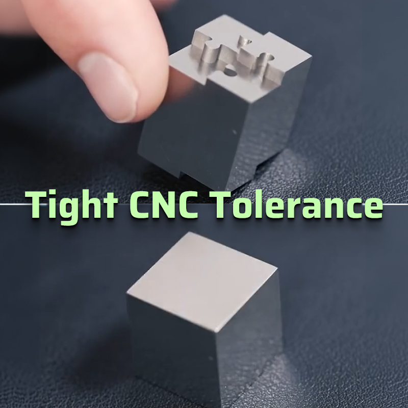
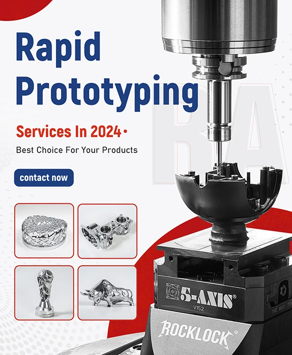
One major role of CNC machining in contemporary manufacturing is to ensure precise machining of all parts with a high degree of repeatability.
Yet, it is almost impossible to have a perfectly dimensioned part. Hence, it brings to light the need for CNC machining tolerance.
Tolerances, in simple terms, are restrictions on the dimensions of a part within permissible variation. They define the acceptable range for deviation from the perfect form of a geometrical product.
For precision machining, it’s crucial to understand CNC machining tolerance.
This guide is your comprehensive resource to understanding CNC machining tolerance. We’ll delve into the different types of tolerances, inspection standards, and how you can optimize the tolerances of your projects.
Key Takeaways
- Understanding CNC machining tolerance and its relation with the manufacturing process.
- In-depth analysis of different types of tolerances, namely general, unilateral, bilateral, and limit tolerances.
- Insight into ISO standards such as ISO 2768 and their role in setting tolerance limits.
- Key considerations for selecting the appropriate tolerance levels based on material, machining methods, and cost.
- Tips for achieving optimal tolerances in CNC machining to ensure part precision and functionality.
Comprender la tolerancia del mecanizado CNC
As discussed, CNC machining tolerance is the allowance of deviation from a respective dimension.
The acceptable variation range of dimensions that will not allow a part from functioning for its intended use—sometimes subtle differences in size, shape, and thickness—are what tolerances are used for.
The controlled allowance for error introduces the relevance of tolerances. Hence, it allows minor imperfections without changing the functionality of a part.
For example, where a part is designed to be of a nominal size of 50 mm and a tolerance of ±0.1 mm, the size of a formed part might fall within the range of 49.9-50.1 mm. This small variation is typically acceptable in most applications.
Importance of Tolerance in CNC Machining
Tolerance is crucial in CNC machining for several reasons:
- Precision and Fit: Tolerances ensure that parts fit together correctly in assemblies. Without proper tolerancing, even minor dimensional variations can lead to parts not fitting, resulting in functional failures.
- Garantía de calidad: Tolerances allow for a threshold of quality to be set in the process of producing parts so that all of those parts are created to spec.
- Cost Control: Tighter tolerances generally lead to higher production costs. This is due to more precise tooling, increased machining time, and stricter quality control. Setting appropriate tolerances lets a manufacturer balance precision and cost-effectiveness.
- Selección del material: Different materials have different reactions to machining processes. Setting the right tolerance helps in accommodating these material-specific behaviors, ensuring consistency across production runs.
Types of CNC Machining Tolerances
There are many types of tolerances applied to CNC machining, each serving some specific purpose depending on a part’s design and function, including:
1. General/Standard Tolerances
General tolerances apply to dimensions that are not explicitly defined in the design specifications.
These tolerances are typically governed by international standards such as ISO 2768, which standardizes the permissible variations in linear and angular dimensions.
- ISO 2768-1: Covers general tolerances for linear and angular dimensions, including sizes like internal and external dimensions, radii, and chamfer heights. Tolerance classes range from fine (f) to very coarse (v).
- ISO 2768-2: Covers geometrical tolerances of features like straightness, circularity, flatness, and cylindricity, with tolerance classes H, K, and L.
These standards are very helpful in cutting down the effort in design and production by avoiding detailed specifications of each feature of the part regarding accepted variations and reducing the rejection of parts.
2. Limit Tolerances
The limit tolerances refer to the maximum and minimum sizes tolerable for a part.
For example, a dimension is indicated to be 12 ± 0.05 mm. To make the part acceptable, it should be between 11.95 and 12.05 mm. This type of tolerance is normally used where high accuracy is required, like in mating parts.
3. Unilateral Tolerances
Unilateral tolerances permit deviation in only one direction from the nominal dimension.
The example used to clarify this point can be a tolerance of 70 +0.00/-0.05 mm. This tolerance clearly indicates that the part is allowed to have a measurement between 70 mm and 69.95 mm but no larger than 70 mm.
Such tolerance is especially called for in those parts that have to fit into a space predefined by other components whose nominal dimension should not be exceeded.
4. Bilateral Tolerances
This type of tolerance allows deviation in both directions from the nominal dimension. For instance, in 30 ± 0.05 mm, a part can measure anywhere between 29.95 and 30.05 mm.
Such types of tolerance are general in nature and are used widely in general manufacturing when small variations on both sides are acceptable.
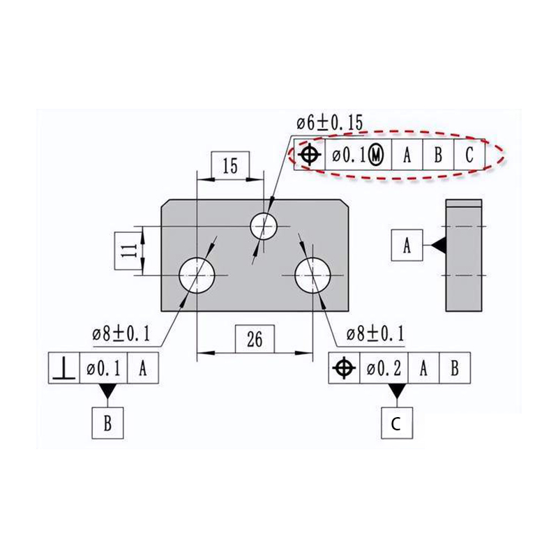
5. GD&T: Geometric Dimensioning and Tolerancing
As an advanced approach, GD&T helps detail how many variances a part’s geometry can have.
Where conventional tolerancing is based on size, GD&T defines the shape, orientation, and location of features from a part.
It makes use of symbols that show specific tolerances for such features as concentricity, flatness, and true position to be followed so that parts meet complicated design requirements.
ISO Standards for CNC Machining Tolerance
ISO standards are very important in defining and standardizing tolerances in CNC machining.
Where ISO 2768 is one of the most commonly used standards, ISO 2768 is more specifically used for geometrical tolerances.
But how are both different and used for precision machining? Let’s uncover.
ISO 2768-1: General Tolerances for Linear and Angular Dimensions
This part of ISO 2768 focuses on simplifying the specification of linear and angular dimensions in technical drawings. It categorizes tolerances into four classes:
- Fine (f)
- Medium (m)
- Coarse (c)
- Very coarse (v)
These are classes for different precision levels. Thus, it enables the designer to choose a suitable class based on the demands that have to be made as per the part and the capability of the manufacturing process.
That implies that a part with a nominal dimension of 100 mm can fall into different classes, with the following ranges:
Fine (f): ±0.15 mm
Medium (m): ±0.3 mm
Coarse (c): ±0.8 mm
Very coarse (v): ±1.5 mm
Linear Dimensions Table
| Gama de dimensiones (mm) | Fine (f) | Medium (m) | Coarse (c) | Very Coarse (v) |
|---|---|---|---|---|
| 0.5 – 3 | ±0,05 mm | ±0,1 mm | ±0.2 mm | ±0.5 mm |
| 3 – 6 | ±0,05 mm | ±0,1 mm | ±0.3 mm | ±0.5 mm |
| 6 – 30 | ±0,1 mm | ±0.2 mm | ±0.5 mm | ±1.0 mm |
| 30 – 120 | ±0.15 mm | ±0.3 mm | ±0.8 mm | ±1.5 mm |
| 120 – 400 | ±0.2 mm | ±0.5 mm | ±1.2 mm | ±2.5 mm |
| 400 – 1000 | ±0.3 mm | ±0.8 mm | ±2.0 mm | ±4.0 mm |
| 1000 – 2000 | ±0.5 mm | ±1.2 mm | ±3.0 mm | ±6.0 mm |
Angular Dimensions Table
| Angle (Degrees) | Fine (f) | Medium (m) | Coarse (c) | Very Coarse (v) |
|---|---|---|---|---|
| Up to 10 mm | ±1° | ±1° | ±1° | ±1° |
| 10 – 50 mm | ±30′ | ±30′ | ±30′ | ±30′ |
| 50 – 120 mm | ±20′ | ±20′ | ±20′ | ±20′ |
| 120 – 400 mm | ±15′ | ±15′ | ±15′ | ±15′ |
| 400 – 1000 mm | ±10′ | ±10′ | ±10′ | ±10′ |
| 1000 – 2000 mm | ±5′ | ±5′ | ±5′ | ±5′ |
ISO 2768-2: Geometrical Tolerances for Features
ISO 2768-2 extends the general tolerances to include geometrical aspects of a part, such as:
- Straightness
- Planitud
- Circularity
- Cylindricity
It defines tolerance classes H, K, and L, which correspond to different levels of precision.
For example, a component specified as ISO 2768-fH must adhere to the fine class for linear dimensions and the H class for geometrical features. This dual-class system ensures that parts meet both dimensional and geometric specifications.
Example Table for Geometrical Tolerances:
Here’s how tolerances might be specified according to the different grades:
| Geometric Feature | Grade H (High Precision) | Grade K (Medium Precision) | Grade L (Low Precision) |
|---|---|---|---|
| Straightness | ≤ 0.02 mm per 100 mm | ≤ 0.05 mm per 100 mm | ≤ 0.1 mm per 100 mm |
| Planitud | ≤ 0.03 mm per 100 mm | ≤ 0.1 mm per 100 mm | ≤ 0.2 mm per 100 mm |
| Circularity | ≤ 0.02 mm | ≤ 0.05 mm | ≤ 0.1 mm |
| Cylindricity | ≤ 0.05 mm | ≤ 0.1 mm | ≤ 0.2 mm |
Key Considerations When Selecting Tolerances
Choosing the right tolerance level is crucial for balancing cost, manufacturability, and part performance.
Here are some key considerations:
Tighter Tolerance Equals Higher Cost
Tighter tolerances require more precise machining, which can significantly increase production costs.
It, therefore, demands lower machining speeds, more specialized tooling, and higher quality control efforts. As such, tolerances should always be established as loose as possible, while the part still serves the desired purpose.
Material Properties
Different materials react differently during the machining process, which can affect the achievable tolerances. Por ejemplo:
- With soft materials, such as plastics, there often is deformation during the machining process.
- With hard materials, like steel or phenolics, cutting tools carry the day since they can easily wear them down, making it hard to get a tight tolerance.
Machining Methods
The choice of machining method can also influence the tolerance levels.
For instance:
- Swiss machining can produce very tight tolerances on a small, multi-featured part without secondary operations
- Milling typically offers tighter tolerances than turning due to the nature of the process.
Selecting the proper machining process to achieve specific tolerances on a component can help improve efficiency and reduce total cost.
Inspección y control de calidad
Parts with tighter tolerances need more elaborate inspection processes, mostly including advanced measurements for which coordinate measuring machines are used.
This adds to the cost and also the time taken to ensure that the parts have the specified tolerances.
Therefore, a reasonable accommodation between the need for precision and the practicality of its quality control is essential in mind when selecting the tolerances.
Tips for Achieving Optimal Tolerances in CNC Machining
Establishing the right tolerances in CNC machining is a collaborative process between proper planning, the use of appropriate tools, and the execution of work with precision.
The following tips aim to have the best possible tolerance for any application:
Understand the Application
Not every part requires tight tolerances. Evaluate the part’s function and determine whether tight tolerances are necessary.
For instance, cosmetic parts or components that don’t interact with other parts often don’t need the same level of precision as functional or mating parts.
Choose the Right Material
Consider the machinability of the material and its behavior under different conditions. Like, metals allow much tighter tolerances than plastics but may require much more robust tools and setups.
Correct selection of the material can lead to great savings in machining work and enable you to obtain the required tolerances.
Use High-Performance Tools
Tool selection is critical in maintaining tolerance levels. Keep cutting tools sharp, maintained, and with an appropriate edge for the material being machined.
For instance, it is necessary to use carbide tools since these exhibit high durability and strength and can ideally maintain a sharp cutting profile, especially for hard materials being machined.
Maintain Workpiece Stability
Machining the workpiece with secure clamping by stable work holders avoids relative movement that would otherwise affect the workpiece’s accuracy with respect to dimensions.
This way, you can ensure the workpiece is correctly supported, and there is a minimum of vibrations or deflections.
Control the Machining Environment
Varying environmental conditions, including temperature and humidity, can influence machining precision.
As an example; thermal expansion in metals can cause dimensional changes. In this case, maintaining a controlled environment can help achieve consistent results.
Common Challenges in Achieving Tight Tolerances
Despite best efforts, achieving tight tolerances in CNC machining can present several challenges.
Let’s explore some such common challenges and how you can avoid them:
- Expansión térmica: Machining generates heat, which can cause materials to expand. This can be particularly problematic when machining parts to tight tolerances, as the dimensions may change as the part cools.
- Tool Wear: Continuous use can wear down cutting tools, leading to dimensional inaccuracies. To avoid this, regular inspection and replacement of tools are essential to maintaining tight tolerances.
- Vibration and Deflection: Machining vibrations may cause the final dimensions to deviate from the intended specifications. The use of dampening methods and secure clamping of the workpiece can minimize such effects.
Conclusión
CNC machining tolerance is a key aspect of precision manufacturing that represents how close a dimension can get to its design specification.
Therefore, proper understanding and selection of appropriate levels of tolerance are critical for ensuring part functionality and maintaining quality while keeping costs down.
By considering material properties, machining methods, and the necessity of part inspection, you can achieve appropriate tolerances. This approach optimizes efficiency while minimizing costs.
Whatever application—be it tight tolerances for critical parts or loose tolerance for general parts—good tolerancing, well thought out, is going to be the hallmark of success in any CNC operation.
As one of the more reliable CNC machining companies, Primer molde has been generating precision-tolerance parts and prototypes for customers across almost every industry. If that’s what you’re looking for, our professional team has you covered!
